
Consumer electronics manufacturers often face a combination of high production volume, compact PCB designs, short product life cycles, frequent model changes, and strong pressure on manufacturing cost.
Products such as:
- Smartphones and accessories
- Smart home devices
- Wearable electronics
- Consumer IoT products
- Audio equipment
- Set-top boxes
- Personal electronics
- Small appliances
- Controllers and interfaces
- Consumer communication devices
can contain highly populated PCBs with small SMT components, fine-pitch ICs, connectors, sensors, LEDs, and other miniature devices.
For these applications, a turnkey SMT line for consumer electronics should not be selected simply by comparing machine specifications.
The complete manufacturing system needs to connect:
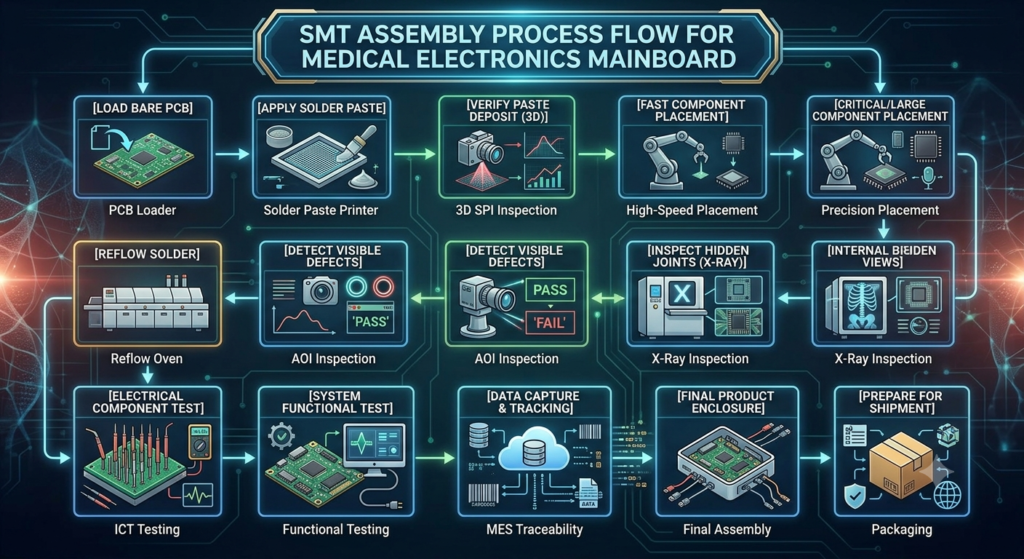
PCB Loading → Solder Paste Printing → SPI → Pick and Place → Reflow → AOI → Testing → PCB Unloading
Depending on the product, the line may also include X-ray inspection, programming, barcode identification, traceability, buffers, cleaning, rework, and production-data integration.
The objective is not simply to install fast machines. It is to create a stable production process that can achieve the required output with appropriate quality, flexibility, and operating cost.
Why Consumer Electronics Need a Specialized SMT Line
Consumer electronics can have particularly demanding production characteristics.
A typical PCB may include:
- 0201 or other miniature passives
- Fine-pitch ICs
- QFPs
- QFNs
- BGAs
- Connectors
- LEDs
- Sensors
- RF components
- Shields
- Battery-related interfaces
At the same time, production may involve:
- High daily volume
- Multiple product models
- Short production cycles
- Frequent engineering changes
- Rapid changeovers
- Tight production schedules
This means SMT equipment must balance speed, accuracy, flexibility, uptime, and changeover performance.

What Does a Turnkey SMT Line Include?
A typical turnkey SMT line may include:
- PCB loader
- Solder paste printer
- SPI system
- Pick and place machine
- Reflow oven
- AOI system
- PCB unloader
Additional equipment can include:
- PCB buffers
- Conveyor systems
- Barcode readers
- X-ray inspection
- Programming stations
- Functional test equipment
- Rework stations
- Cleaning equipment
- Nitrogen systems where required
- MES/traceability integration
The exact configuration should depend on the product and target production capacity.
Start with PCB and BOM Analysis
The first step should be technical analysis rather than equipment selection.
Prepare:
- PCB dimensions
- PCB thickness
- Panel dimensions
- PCB weight
- BOM
- Component packages
- Number of placements
- Smallest component
- Largest component
- Component height
- Special components
- Target production volume
- Product mix
Also determine whether the PCB contains:
- BGA
- QFN
- Fine-pitch devices
- Bottom-side components
- Odd-form components
- Connectors
- Shields
- Components requiring special handling
This information determines the appropriate SMT equipment configuration.
Typical Turnkey SMT Production Flow
A standard automated line may be:
Automatic PCB Loader → Solder Paste Printer → SPI → Pick and Place Machine(s) → Reflow Oven → AOI → PCB Unloader
For a more advanced production environment:
PCB Loader → Printer → SPI → Placement → Reflow → AOI → Buffer → Testing → Unloader
Barcode and production-data systems can be integrated where traceability is required.
Step 1: Automatic PCB Loading
The loader transfers PCBs into the SMT line.
Important considerations include:
- PCB dimensions
- Board thickness
- Board weight
- Panel configuration
- Conveyor width
- Production speed
- Board separation requirements
For high-volume consumer electronics, automated material handling can reduce manual intervention.
Step 2: Solder Paste Printing
Printing is one of the most important processes in SMT assembly.
The printer should provide controlled:
- Alignment
- Squeegee movement
- Printing pressure
- Separation
- Stencil cleaning
- PCB support
For miniature components, stencil design and solder paste control become particularly important.
Potential printing problems include:
- Insufficient paste
- Excess paste
- Offset
- Bridging
- Inconsistent deposits
A high-speed placement machine cannot compensate for unstable solder paste printing.
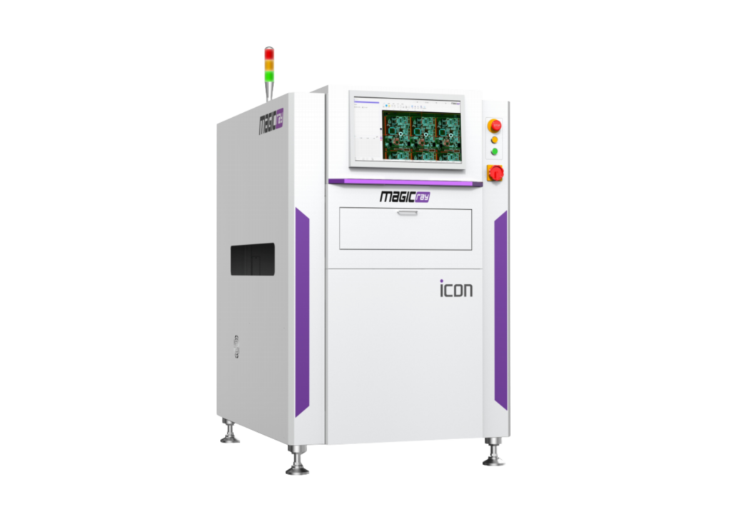
Step 3: SPI Inspection
SPI can inspect solder paste before component placement.
Typical measurements include:
- Volume
- Height
- Area
- Position
SPI allows manufacturers to identify printing-related problems earlier in the process.
For high-density consumer electronics PCBs, SPI can be particularly useful because many small solder deposits may be difficult to evaluate reliably through manual inspection.
Step 4: Pick and Place
The placement section is often the most visible part of an SMT line.
However, machine selection should not be based only on maximum CPH.
Evaluate:
- Component range
- Placement accuracy
- Feeder capacity
- Feeder changeover
- Tray handling
- Component recognition
- PCB dimensions
- Component height
- Placement quantity
- Product mix
- Placement Capacity Example
Suppose a consumer electronics PCB contains:
- 600 SMT placements
- and the required production rate is:
- 120 boards/hour
- The theoretical placement requirement is:
- 600 × 120 = 72,000 placements/hour
However, purchasing a machine simply because its rated speed exceeds 72,000 CPH may be inappropriate.
Actual capacity is influenced by:
- Component mix
- Feeder locations
- Component recognition
- Travel distance
- Tray components
- PCB transfer
- Changeover
- Machine utilization
The correct machine configuration should therefore be calculated from the actual BOM.
High-Speed vs Flexible Placement
Consumer electronics factories may need a combination of placement capabilities.
High-Speed Placement
Useful when the PCB contains large quantities of:
- Resistors
- Capacitors
- Small passive components
Flexible Placement
Important when the PCB includes:
- ICs
- Connectors
- Larger components
- Fine-pitch components
- Odd-form or specialized components
A combination of high-speed and flexible placement machines can sometimes provide a better balance than relying on a single machine type.
Feeder Capacity Matters
Feeders can become a significant operational factor.
A line may have enough theoretical placement capacity but still suffer from:
- Frequent feeder changes
- Poor feeder organization
- Material shortages
- Long changeovers
- Excessive setup work
For high-volume consumer electronics, feeder configuration and material preparation should be considered part of line productivity.
Step 5: Reflow Soldering
After component placement, the PCB enters the reflow oven.
A reflow oven typically provides controlled thermal zones for the soldering process.
The actual profile depends on:
- Solder paste
- PCB construction
- Component requirements
- Copper distribution
- Thermal mass
There is no universal reflow profile for every consumer electronics PCB.
Thermal profiling should be performed using the actual PCB and process materials.
Nitrogen Reflow: Is It Always Necessary?
No.
Nitrogen may be considered when the soldering process or product requirements justify it.
The decision should consider:
- Solder paste
- PCB design
- Component requirements
- Oxidation considerations
- Process capability
- Operating cost
Nitrogen should not automatically be included simply because the product is consumer electronics.
Step 6: AOI Inspection
AOI can inspect visible assembly characteristics such as:
- Missing components
- Component position
- Orientation
- Polarity
- Certain solder-joint conditions
- AOI can help identify defects after reflow.
However, optical inspection has limitations when solder joints are hidden beneath packages.
When Is X-Ray Needed?
X-ray may be considered for:
- BGA
- Selected QFN applications
- Hidden solder structures
Whether X-ray should be inline, offline, sampling-based, or omitted depends on the product and inspection strategy.
Not every consumer electronics PCB requires 100% X-ray inspection.
Step 7: Testing
SMT inspection does not replace electrical or functional testing.
Depending on the product, testing may include:
- ICT
- Flying probe
- Programming
- Functional testing
- Communication testing
- Display testing
- Sensor testing
- Product-specific electrical tests
For consumer electronics, functional testing can become an important production bottleneck.
Testing Bottleneck Example
Consider:
The practical finished-product capacity is approximately:
60 boards/hour
Increasing placement capacity from 180 to 220 boards/hour would not solve the production constraint.
Parallel Testing
Suppose:
- Test time = 60 seconds
- Required takt time = 20 seconds
A simplified estimate is: 60 ÷ 20 = 3 test positions
Actual requirements should also consider:
- Loading
- Unloading
- Retesting
- Operator handling
- Test fixture availability
Testing capacity should therefore be included in the turnkey line design.
High-Mix Consumer Electronics Manufacturing
Not every consumer electronics factory operates a single high-volume product.
Some manufacturers produce:
- Multiple models
- Different PCB revisions
- Different component variants
- Small and medium batches
In this environment, line flexibility becomes important.
Consider:
- Feeder capacity
- Offline setup
- Quick changeover
- Recipe management
- Barcode verification
- Automatic product identification
- Flexible placement equipment
A slightly slower machine with significantly better changeover performance may sometimes deliver more usable production capacity.
Fast Changeover
Changeover time can include:
- Stopping the line
- Removing feeders
- Loading new feeders
- Preparing materials
- Loading the new program
- Verifying components
- Running the first boards
- Confirming quality
Offline feeder preparation can reduce the time that the main production line remains idle.
Recipe and Program Management
A turnkey SMT line may involve programs for:
- Printer
- SPI
- Placement machines
- Reflow
- AOI
- Barcode system
- Testing equipment
Product identification can help ensure that the correct recipe is loaded.
This becomes increasingly important when factories manufacture multiple product models.
PCB Handling and Buffers
Buffers can be used between selected processes to help manage temporary capacity differences.
For example:
Placement → Buffer → Reflow → Buffer → AOI
can provide additional flexibility when process cycle times or downtime patterns differ.
However, excessive WIP is not automatically beneficial.
Too much WIP can:
- Hide bottlenecks
- Increase material handling
- Consume floor space
- Delay defect detection
Buffers should therefore be sized according to actual production requirements.
Traceability
Consumer electronics manufacturers may require different levels of production traceability.
Potential data can include:
- PCB serial number
- Product model
- PCB revision
- Production time
- Machine
- Program
- Component/material information
- Solder paste lot
- SPI results
- Reflow data
- AOI results
- Test results
Barcode or QR-code systems can connect data across the line.
The required level depends on the product and customer requirements.
MES and Production Data Integration
For larger factories, SMT equipment may be integrated with production-management systems.
Potential functions include:
- Product identification
- Recipe management
- Production reporting
- Machine status
- Material tracking
- Quality data
- Traceability
The integration level should match the factory’s digitalization strategy.
Rework and Defect Handling
A turnkey SMT line should also consider what happens when a board fails inspection.
A basic flow can include:
Production → Inspection → NG Identification → Rework → Re-inspection → Testing
A dedicated rework area can help prevent defective boards from returning to the main production flow without proper control.
Common SMT Defects in Consumer Electronics
Potential SMT defects include:
- Solder bridges
- Insufficient solder
- Missing components
- Misalignment
- Tombstoning
- Polarity errors
- Component damage
- Voiding in selected applications
Root-cause analysis should consider:
Printing + Placement + Reflow + Components + PCB + Inspection
rather than assuming that the placement machine is always responsible.
Line Balancing
A turnkey SMT line should be balanced around the complete process.
Evaluate:
Printing → SPI → Placement → Reflow → AOI → Testing
Useful metrics include:
- Takt time
- Cycle time
- First-pass yield
- Changeover time
- Downtime
- WIP
- Rework
- Equipment utilization
The fastest machine does not necessarily create the fastest production line.
Example of Line Balancing
Suppose:
The line is effectively limited to approximately: 100 boards/hour
because testing is the bottleneck.
Factory Layout for a Turnkey SMT Line
A practical SMT factory may include:
- Incoming material area
- PCB storage
- Component warehouse
- SMT production
- Inspection
- Testing
- Rework
- Finished PCBA area
Material flow should be designed to reduce unnecessary movement.
Maintenance access should also be considered before finalizing machine positions.
Factory Utilities
Depending on the equipment, utilities can include:
- Electrical power
- Compressed air
- Exhaust
- HVAC
- Nitrogen where required
- Network connections
- Reflow ovens, solder paste printers, inspection equipment, and other machines may have specific utility requirements.
- Utility capacity should be checked before installation.
New vs Pre-Owned SMT Equipment
A turnkey line does not necessarily need to consist entirely of new machines.
A hybrid configuration can combine:
- New equipment for critical processes
- Suitable pre-owned equipment for selected applications
- New inspection systems
- Existing factory equipment
Pre-owned equipment should be evaluated for:
- Machine condition
- Placement accuracy
- Camera systems
- Heads
- Feeders
- Sensors
- Software
- Conveyor condition
- Maintenance history
- Spare-parts availability
- Technical support
The objective is to achieve the required process capability and total cost of ownership.
Equipment Selection by Production Scale
High-Mix / Lower-Volume
A possible configuration:
Loader → Printer → SPI → Flexible Placement → Reflow → AOI → Testing
Priorities:
- Flexibility
- Fast changeover
- Feeder capacity
- Recipe management
- Medium-Volume
A possible configuration:
Loader → Printer → SPI → Flexible/High-Speed Placement → Reflow → AOI → Testing
Priorities:
- Balanced capacity
- Automation
- Changeover
- Process control
- High-Volume
A possible configuration:
Automatic Loading → Printer → SPI → Multiple Placement Machines → Reflow → AOI → Testing → Unloading
Priorities:
- High effective throughput
- Uptime
- Automation
- Parallel testing
- Material logistics
- Traceability
How Fuliu Electronics Supports SMT Production Line Planning
Established in 2014, Fuliu Electronics is dedicated to providing customers with high-quality PCBA intelligent manufacturing solutions and services.
With extensive SMT industry experience, Fuliu Electronics specializes in dependable equipment, professional technical support, and complete SMT production line solutions.
Our equipment portfolio includes SMT pick and place machines from Fuji, Panasonic, ASM, Yamaha, JUKI, and Hanwha, as well as ERSA reflow ovens from Germany, MagicRay SPI/AOI inspection systems, automatic solder paste printers, supporting equipment, pre-owned SMT equipment, SMT spare parts, machine leasing, and maintenance services.
For consumer electronics manufacturers, we can help evaluate the complete production process:
PCB Loading → Printing → SPI → Placement → Reflow → AOI → Testing
Planning can consider:
- PCB dimensions
- BOM
- Component range
- Placement quantity
- Target capacity
- Product mix
- Changeover requirements
- Inspection
- Testing
- Traceability
- Existing equipment
- Factory layout
- Automation level
- New/pre-owned equipment
- Investment budget
Fuliu Electronics is also expanding its international market presence, with key focus markets including India, Vietnam, the Philippines, Indonesia, the Middle East, South Africa, and Europe.
Frequently Asked Questions
A typical line includes a PCB loader, solder paste printer, SPI, pick and place machine, reflow oven, AOI, and PCB unloader. Testing, X-ray, buffers, barcode systems, and other equipment can be added according to requirements.
Start with placements per PCB, target boards per hour, product mix, component range, and testing requirements. Calculate effective capacity rather than relying only on machine-rated CPH.
SPI is not universally mandatory, but it can provide useful process information about solder paste volume, height, area, and position, especially on dense SMT boards.
No. X-ray is generally considered when hidden solder structures, such as selected BGA or QFN applications, require additional inspection.
Very important. Insufficient feeder capacity or inefficient feeder setup can increase changeover time and reduce actual production availability.
For higher production volumes, multiple machines can provide higher effective placement capacity and broader component coverage. The exact configuration should be based on the BOM and target output.