
Power supply manufacturing creates a unique set of PCB assembly challenges.
Unlike many compact consumer electronics boards dominated by small surface-mount components, power supply PCBAs often combine:
- Fine-pitch SMT components
- Controllers and driver ICs
- Resistors and capacitors
- Power semiconductors
- Large electrolytic capacitors
- Transformers
- Inductors
- Relays
- Connectors
- Terminal blocks
- Heat sinks
- Other large or mechanically demanding components
As a result, a reliable PCB assembly solution for power supply manufacturing often requires both SMT and THT processes.
A typical mixed-technology production flow may be:
Solder Paste Printing → SPI → SMT Placement → Reflow → AOI → THT Insertion → Wave or Selective Soldering → Inspection → Testing
The correct production line depends on the PCB design, BOM, power level, component mix, target capacity, product variety, quality requirements, and factory layout.
This guide explains how to configure an effective PCBA production solution for power supply manufacturing.
Why Power Supply PCB Assembly Is Different
Power supply boards often contain a wider range of component sizes than many other electronics products.
A single PCB may combine small passive components with large magnetic and power components.
This creates several manufacturing challenges:
- Large variation in component dimensions
- Different component packaging formats
- High thermal mass
- Heavy through-hole components
- Mixed SMT and THT processes
- Large solder joints
- Heat-sensitive components
- Mechanical assembly requirements
- Electrical safety and testing requirements defined by the product
For this reason, production equipment should be selected according to the complete process rather than only SMT placement speed.
Typical Power Supply PCB Applications
PCB assembly solutions may be required for power supplies used in:
- Industrial automation
- Communication equipment
- LED systems
- Consumer electronics
- Home appliances
- Energy equipment
- Automotive electronics
- Charging equipment
- Data and network systems
- Medical and laboratory equipment
- Factory machinery
The exact PCBA process can vary significantly between a compact switching power supply and a large industrial power module.
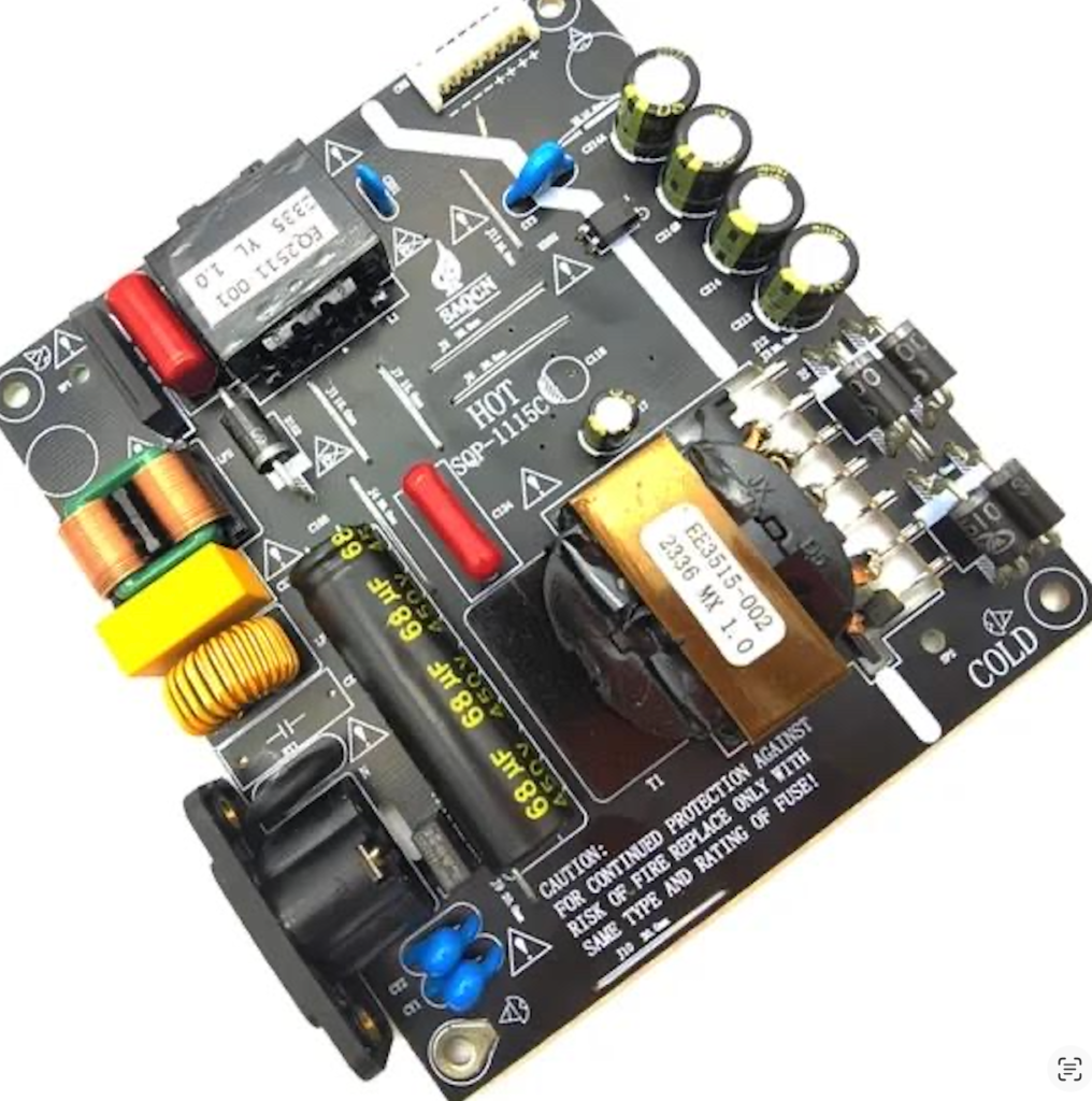
Common Components on Power Supply PCBs
Understanding the BOM is the first step in production line design.
SMT Components
Typical surface-mount components can include:
- Chip resistors
- Ceramic capacitors
- Diodes
- Transistors
- MOSFETs
- Control ICs
- Driver ICs
- Optocouplers
- Small inductors
- QFN, QFP, SOIC, and other semiconductor packages
These components are generally processed on an SMT line.
THT Components
Through-hole components may include:
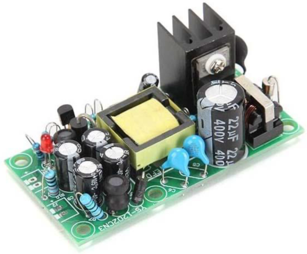
- Transformers
- Large electrolytic capacitors
- Large inductors
- Relays
- Terminal blocks
- Connectors
- Fuses
- Power resistors
- Selected power semiconductor packages
These components usually require additional THT insertion and soldering processes after SMT assembly.
Heat Sinks and Mechanical Parts
Some power supply PCBAs also require:
- Heat sinks
- Clips
- Screws
- Insulators
- Thermal interface materials
These operations may occur after soldering or during final assembly depending on product design.
Recommended Power Supply PCBA Process Flow
A complete mixed SMT + THT production process can be:
PCB Loader → Automatic Solder Paste Printer → SPI → SMT Pick and Place → Reflow Oven → AOI → THT Component Preparation → THT Insertion → Pre-Solder Inspection → Wave or Selective Soldering → Post-Solder Inspection → Electrical Testing → Functional Testing
Additional operations can be added where required.
Step 1: PCB Loading
Automatic PCB loaders can improve material flow and reduce manual board handling.
Important selection factors include:
- PCB dimensions
- Panel size
- PCB thickness
- Board weight
- Magazine size
- Production direction
The loader should be compatible with downstream SMT equipment.
Step 2: Automatic Solder Paste Printing
Solder paste printing is one of the most important SMT process stages.
The printer applies solder paste through a stencil onto PCB pads.
Important process factors include:
- Stencil design
- Solder paste condition
- Print pressure
- Print speed
- Separation parameters
- PCB support
- Stencil cleaning
Power supply boards may have different pad sizes and thermal structures, so stable printing is essential.
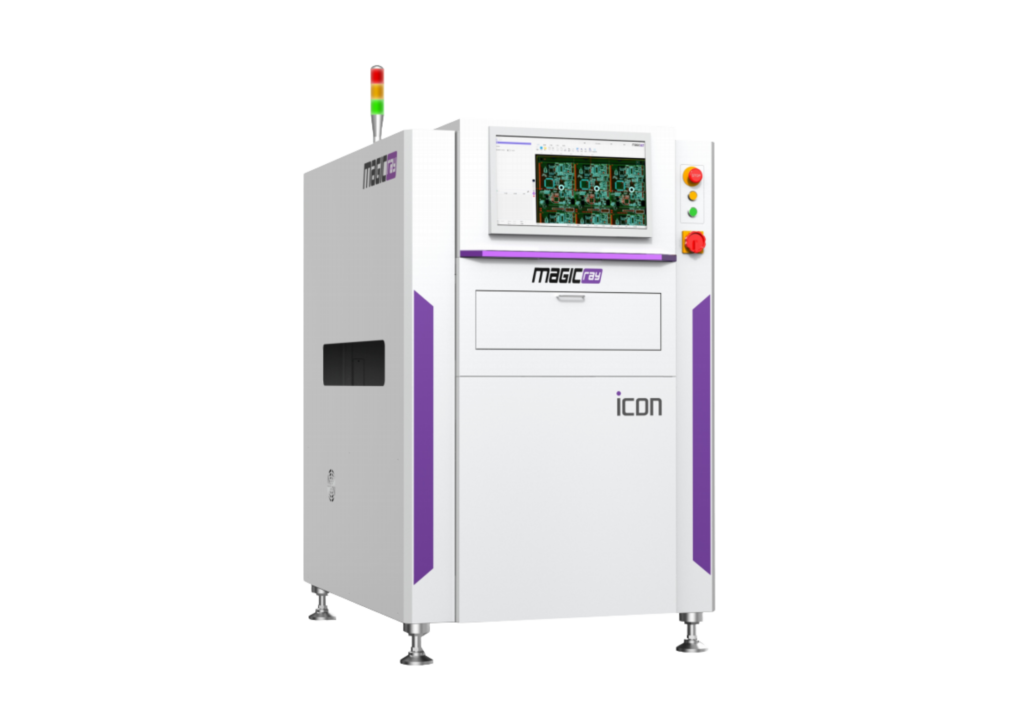
Step 3: SPI Inspection
SPI, or Solder Paste Inspection, checks deposited solder paste before component placement.
It can help detect:
- Insufficient paste
- Excess paste
- Offset
- Poor print shape
- Missing deposits
Finding printing problems before placement and reflow can reduce downstream defects.
Step 4: SMT Pick and Place
The placement system installs surface-mount components onto the printed PCB.
Power supply production may require placement of both:
- Small passive components
- Larger SMT power devices
When choosing a pick and place machine, manufacturers should consider:
- Component size range
- Required feeders
- Placement accuracy
- Board dimensions
- Actual component mix
- Production capacity
- Product changeover frequency
Machine rated speed should not be treated as actual line output.
Step 5: Reflow Soldering
After component placement, the PCB enters the reflow oven.
A typical reflow process includes thermal stages such as:
Preheating → Thermal Equalization → Reflow → Cooling
Power supply PCBs can present additional thermal challenges because of:
- Thick copper
- Large pads
- Large power components
- Heavy copper areas
- Uneven thermal mass
The reflow profile should therefore be developed according to:
- Solder paste
- PCB construction
- Components
- Thermal mass
- Product requirements
There is no universal reflow profile suitable for every power supply PCB.
Why Reflow Oven Selection Matters
A suitable reflow oven should provide:
- Stable temperature control
- Appropriate heating length
- Controlled conveyor
- Suitable cooling
- Recipe management
For products with significant thermal mass, oven capacity and thermal uniformity can be particularly important.
Step 6: AOI Inspection
AOI can inspect SMT assembly after reflow.
Typical inspection targets include:
- Missing components
- Wrong components
- Polarity
- Offset
- Tombstoning
- Certain solder joint conditions
AOI does not replace electrical testing, but it can help identify visible assembly defects before the board enters THT processing.
Step 7: THT Component Preparation
Many power supply boards contain components that require preparation before insertion.
Possible operations include:
- Lead cutting
- Lead forming
- Bending
- Straightening
- Kitting
Components may include:
- Resistors
- Capacitors
- Diodes
- Transformers
- Inductors
Component preparation should be integrated into line balancing.
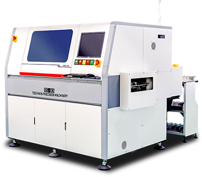
Step 8: THT Component Insertion
THT insertion may be:
- Manual
- Semi-automatic
- Automatic
Manual insertion remains common for large and irregular power components.
Examples include:
- Transformers
- Large electrolytic capacitors
- Relays
- Terminal blocks
- Large connectors
- Large inductors
Automatic insertion may be suitable for more standardized through-hole components with compatible packaging.
For many power supply factories, a hybrid model works well:
Automatic insertion for suitable components + manual insertion for large or irregular components
Step 9: Pre-Solder Inspection
Before soldering, the PCB should be checked for:
- Missing parts
- Wrong components
- Incorrect polarity
- Incorrect orientation
- Component height
- Bent leads
- Improper insertion
This is especially important for polarized components such as electrolytic capacitors.
Detecting errors before soldering reduces rework.
Step 10: Wave Soldering
Wave soldering is commonly used when the PCB contains many THT joints.
The process generally includes:
Fluxing → Preheating → Solder Wave → Cooling
Important variables include:
- Flux application
- Preheat
- Solder temperature
- Conveyor speed
- Wave stability
- PCB orientation
- Board design
- Component solderability
Power supply boards can have high thermal mass, which may influence solder filling and process stability.
The soldering recipe should therefore be optimized for the actual PCB.
Step 11: Selective Soldering
Selective soldering may be preferable when:
- Only selected THT joints require soldering
- Bottom-side SMT components restrict wave soldering
- PCB geometry is complex
- Certain areas should avoid broad solder contact
A selective soldering process typically includes:
Selective Fluxing → Preheating → Programmed Soldering
For mixed-technology power supply boards, selective soldering can provide useful process flexibility.
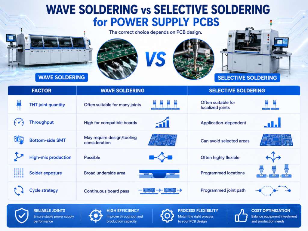
Wave Soldering vs Selective Soldering for Power Supply PCBs
The correct choice depends on PCB design.
Neither method is universally better.
Step 12: Post-Solder Inspection
After THT soldering, inspect the board for defects such as:
- Solder bridges
- Poor wetting
- Insufficient solder
- Incomplete hole fill
- Excessive solder
- Icicles
- Solder balls
Power supply boards with larger thermal masses may require particular attention to hole fill and solder wetting.
Inspection can include:
- Visual inspection
- Magnification
- AOI where applicable
- X-ray where hidden structures justify it
Step 13: Electrical Testing
Testing is an essential part of power supply manufacturing.
Depending on the product, tests may include:
- ICT
- Continuity testing
- Functional testing
- Voltage output testing
- Current output testing
- Communication testing
- Protection-function testing
Higher-voltage or safety-related testing must be performed according to the product’s design requirements, applicable standards, and factory procedures.
Testing equipment and safety controls should be planned separately for the actual power supply design.
Why Testing Can Become the Bottleneck
Suppose the assembly line can produce:
- SMT: 80 boards/hour
- THT insertion: 45 boards/hour
- Wave soldering: 70 boards/hour
- Inspection: 55 boards/hour
- Functional testing: 25 boards/hour
Finished output cannot exceed the effective testing capacity.
In this example, testing is the bottleneck.
The factory may need:
- Multiple test stations
- Parallel fixtures
- Better test automation
- Improved material flow
Production line planning should include testing from the beginning.
High Thermal Mass Is a Key Manufacturing Challenge
Power supply PCBs often include components and copper structures with significant thermal mass.
Examples include:
- Transformers
- Large inductors
- Heavy copper areas
- Large power pads
- Thick PCBs
These features can affect both:
- Reflow soldering
- Wave or selective soldering
Process engineers should monitor actual PCB temperatures and develop suitable process windows rather than relying only on machine setpoints.
Heavy Copper PCB Considerations
Some power electronics boards use heavier copper than standard signal boards.
This may influence:
- Heat transfer
- Reflow profiling
- THT hole fill
- Cooling behavior
- Soldering time
The PCB specification should therefore be reviewed during production line planning.
Large Component Handling
Large components can create issues such as:
- Component tilting
- Movement before soldering
- Inconsistent insertion depth
- Difficult manual handling
Fixtures or work instructions may be needed to stabilize selected components before soldering.
The production line should provide sufficient working space for operators handling large THT parts.
How to Configure the SMT Line
A typical SMT section can be:
PCB Loader → Solder Paste Printer → SPI → Pick and Place Machine(s) → Reflow Oven → AOI → PCB Unloader/Buffer
The exact configuration depends on production demand.
Low-to-Medium Volume Power Supply Production
Typical priorities include:
- Flexibility
- Fast changeover
- Broad component handling
- Moderate equipment investment
A configuration may use:
- One automatic printer
- One SPI
- One flexible pick and place machine
- One reflow oven
- One AOI
This can work well for high-mix production.
Higher-Volume Power Supply Production
Higher-volume factories may require:
- Multiple pick and place machines
- Higher feeder capacity
- More automated material handling
- Larger buffer capacity
- Higher inspection throughput
- Integrated traceability
The line should be balanced based on actual BOM placement time.
How to Configure the THT Line
A typical THT section can include:
Component Preparation → Insertion Stations → Inspection Conveyor → Wave/Selective Soldering → Cooling → Inspection → Testing
For products containing many large components, the insertion area can become the bottleneck.
Manufacturers may need:
- Multiple parallel workstations
- Better component kitting
- Improved ergonomic layout
- Automated preparation
- Automatic insertion for suitable parts
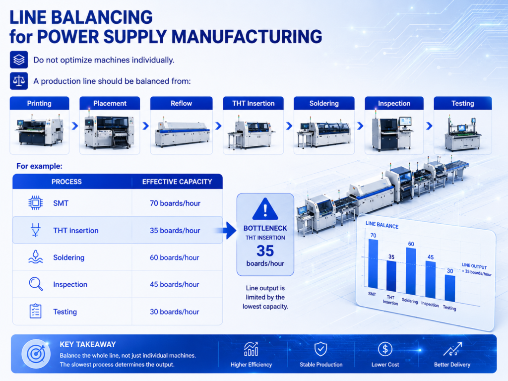
Line Balancing for Power Supply Manufacturing
Do not optimize machines individually.
A production line should be balanced from:
Printing → Placement → Reflow → THT Insertion → Soldering → Inspection → Testing
The finished line is limited to around 30 boards/hour unless the testing bottleneck is improved.
Higher SMT speed alone would not increase finished output.
High-Mix vs High-Volume Power Supply Production
High-Mix Manufacturing
Typical requirements include:
- Flexible feeder setup
- Fast recipe changeover
- Adjustable conveyors
- Manual THT flexibility
- Easy program management
- Flexible testing fixtures
A semi-automatic production model may be more economical.
High-Volume Manufacturing
Typical priorities include:
- Automated loading
- Higher placement capacity
- Automatic THT insertion where practical
- Automated soldering
- Automatic inspection
- Traceability
- Parallel testing
The best solution depends on product stability and production volume.
New vs Pre-Owned SMT Equipment
Power supply manufacturers can consider:
- New SMT equipment
- Pre-owned SMT equipment
- Hybrid lines
A hybrid line may combine new and carefully selected pre-owned machines according to process requirements.
When evaluating pre-owned equipment, review:
- Machine condition
- Software
- Feeder availability
- Accuracy
- Maintenance history
- Spare parts
- Technical support
The decision should be based on total cost of ownership rather than purchase price alone.
Factory Layout for Power Supply PCB Assembly
Factory layout affects both productivity and material flow.
Important areas include:
- Incoming PCB storage
- SMT production
- Component storage
- THT preparation
- Manual insertion
- Wave/selective soldering
- Inspection
- Testing
- Rework
- Finished goods
- Maintenance access
A typical flow should minimize unnecessary movement and WIP.
For example:
Material Preparation → SMT → THT → Soldering → Inspection → Testing → Final Assembly
Material Management for Power Supply Production
Power supply BOMs often contain many component types with significant size differences.
Material management should address:
- SMT reels
- Trays
- Tubes
- Radial components
- Large transformers
- Connectors
- Mechanical parts
Good kitting can improve manual THT insertion efficiency significantly.
Traceability
Depending on product and customer requirements, traceability may include:
- PCB serial number
- Production date
- Machine program
- Component lot
- Solder paste lot
- Inspection results
- Reflow process data
- THT soldering data
- Test results
The required level of traceability varies by application.
It should be determined before equipment and software architecture are finalized.
Common Power Supply PCB Assembly Challenges
Insufficient Solder Paste
Large pads or poor printing conditions can contribute to insufficient solder.
SPI can help detect printing variation before placement.
Component Misalignment
Larger components may require suitable nozzle selection and placement support.
Reflow Profile Imbalance
Large thermal differences across the PCB can make reflow profiling more challenging.
Poor THT Hole Fill
High thermal mass, solderability, flux, preheat, and process contact can all influence hole fill.
Solder Bridges
Dense THT connectors or inappropriate board orientation can contribute to bridging during wave soldering.
Incorrect Polarity
Electrolytic capacitors, diodes, and selected connectors require clear polarity control.
Test Bottlenecks
As assembly automation improves, testing can become the slowest stage.
How to Improve Process Stability
A stable power supply PCBA process requires control across the whole line.
Important practices include:
- Validate solder paste printing
- Use SPI where appropriate
- Maintain feeders and placement nozzles
- Develop a suitable reflow profile
- Control THT component preparation
- Standardize manual insertion
- Inspect polarity before soldering
- Control wave/selective soldering parameters
- Maintain soldering equipment
- Use structured defect analysis
- Balance test capacity
- Train operators and technicians
What Data Is Needed to Configure a Power Supply PCB Assembly Line?
Before requesting a production line proposal, manufacturers should prepare:
- PCB dimensions
- PCB thickness
- Copper specification where relevant
- BOM
- SMT component list
- THT component list
- Component packaging
- Component photos or datasheets where useful
- Maximum component height
- Maximum component weight
- Target production capacity
- Product mix
- Number of shifts
- Wave or selective soldering requirements
- Inspection requirements
- Testing requirements
- Traceability requirements
- Existing equipment
- Factory layout
- Utilities
- Desired automation level
- Investment budget
The more complete the production data, the more accurately the line can be configured.
Three Typical Power Supply PCB Assembly Configurations
Configuration 1: High-Mix / Low-to-Medium Volume
Printer → SPI → Flexible Pick and Place → Reflow → AOI → Manual THT Insertion → Wave/Selective Soldering → Manual Inspection → Functional Testing
Suitable for:
- Multiple product models
- Frequent changeovers
- Moderate output
Main priority: Flexibility
Configuration 2: Medium-Volume Semi-Automatic Line
Automatic Loader → Printer → SPI → Pick and Place → Reflow → AOI → Automated PCB Transfer → Semi-Automatic THT Area → Wave Soldering → Inspection → Parallel Testing
Suitable for:
- Growing production volume
- Stable product families
- Factories seeking labor reduction
Main priority: Balanced automation
Configuration 3: High-Volume Production Line
Automatic Loading → Printing → SPI → Multiple Pick and Place Machines → Reflow → AOI → Automatic/Semi-Automatic THT Insertion → Automatic Soldering → Inspection → Automated/Parallel Testing → Traceability
Suitable for:
- Higher-volume production
- Stable product demand
- Repetitive BOM structures
Main priority: Throughput and process consistency
PCB Assembly Solutions from Fuliu Electronics
Established in 2014, Fuliu Electronics is dedicated to providing customers with high-quality PCBA intelligent manufacturing solutions and services.
With extensive experience in the SMT industry, we specialize in dependable equipment, professional technical support, and complete SMT and PCBA production line solutions.
Our product portfolio includes SMT pick and place machines from Fuji, Panasonic, ASM, Yamaha, JUKI, and Hanwha, together with ERSA reflow ovens from Germany, MagicRay SPI/AOI inspection systems, automatic solder paste printers, supporting PCBA equipment, pre-owned SMT equipment, SMT spare parts, machine leasing, and maintenance services.
For power supply manufacturers planning a new PCBA line or upgrading an existing factory, Fuliu Electronics can help evaluate:
- PCB dimensions
- BOM
- SMT/THT component mix
- Large component requirements
- PCB thermal characteristics
- Target production capacity
- Product variety
- Wave vs selective soldering
- Inspection requirements
- Testing requirements
- Existing equipment
- Factory layout
- Automation level
- Investment budget
Rather than selecting machines independently, manufacturers can plan SMT, THT, soldering, inspection, material handling, and testing as one complete production system.
As part of our global growth strategy, Fuliu Electronics is actively expanding into international markets, with key focus areas including India, Vietnam, the Philippines, Indonesia, the Middle East, South Africa, and Europe.
Conclusion
A reliable PCB assembly solution for power supply manufacturing should be built around the actual product rather than a standard machine list.
Power supply PCBAs often combine:
- High-density SMT components
- Large power devices
- Transformers and inductors
- Large capacitors
- Connectors and terminal blocks
- Mixed SMT and THT processes
- Complex thermal requirements
- Electrical and functional testing
A typical production flow is:
Solder Paste Printing → SPI → SMT Placement → Reflow → AOI → THT Insertion → Wave/Selective Soldering → Inspection → Testing
For high-mix production, flexibility and fast changeover may be more valuable than maximum automation.
For higher-volume production, automatic handling, greater placement capacity, THT automation, traceability, and parallel testing may provide more value.
Most importantly, the line should be balanced from SMT assembly through final testing.
A fast pick and place machine cannot improve finished output if THT insertion, soldering, or electrical testing remains the bottleneck.
If you are planning a new power supply PCB assembly line, expanding a power electronics factory, or upgrading an existing SMT + THT PCBA production process, Fuliu Electronics can help evaluate your PCB dimensions, BOM, component mix, thermal characteristics, target capacity, soldering process, testing requirements, factory layout, automation level, existing equipment, and investment budget to develop a suitable production line solution.
Frequently Asked Questions
SMT is suitable for high-density electronic components, while many power supply boards also use larger components such as transformers, connectors, relays, large capacitors, and terminal blocks that may use through-hole mounting.
A common process is solder paste printing, SPI, SMT placement, reflow, AOI, THT insertion, wave or selective soldering, inspection, and testing.
Yes, especially when a PCB contains many through-hole joints and the board design is compatible with wave soldering.
Selective soldering can be useful when only localized THT joints require soldering or bottom-side SMT components restrict broad wave contact.
Large components, heavy copper areas, thick boards, and uneven thermal mass can make thermal profiling more challenging.
Some can, depending on component packaging, machine capability, dimensions, weight, and feeder availability. Others may still require manual or semi-automatic insertion.