
Automotive electronics are used across a wide range of vehicle systems, from body control and lighting to power management, battery systems, infotainment, sensors, charging, and other electronic modules.
Depending on their location and product design, these PCB assemblies may be exposed to environmental conditions such as:
- Humidity
- Condensation
- Dust
- Temperature variation
- Certain chemical contaminants
- Corrosive environments
- Vibration and mechanical stress at the product level
For some automotive PCBAs, conformal coating is used as an additional protective process after PCB assembly and testing.
A typical coating process may include:
PCBA Inspection → Cleaning/Surface Preparation → Masking/Keep-Out Control → Selective Coating → Inspection → Flash-Off → Curing → Final Inspection
However, not every automotive PCBA requires conformal coating, and not every coating material or process is suitable for every automotive application.
The correct solution depends on the PCB design, operating environment, customer specification, coating chemistry, process requirements, production capacity, and factory layout.
Conformal Coating Solution for Automotive PCBA
This guide explains how to configure a practical conformal coating solution for automotive PCBA manufacturing.
Why Automotive PCBAs May Require Conformal Coating
Automotive electronics can operate in very different environments depending on where the electronic module is installed.
For example, PCBAs used in:
- Passenger compartments
- Engine-related systems
- Exterior lighting
- Battery systems
- Power electronics
- Charging systems
may experience very different levels of moisture, heat, contamination, or thermal cycling.
Where appropriate, conformal coating can help provide an additional protective barrier over selected PCB surfaces.
Potential benefits can include improved resistance to:
- Moisture
- Humidity
- Condensation
- Dust
- Certain contaminants
- Corrosive exposure
The actual performance depends on the coating material, thickness, coverage, curing quality, PCB cleanliness, enclosure, and product design.
Conformal coating should not be treated as a substitute for good PCB design, reliable soldering, proper sealing, thermal management, or mechanical design.
What Is Conformal Coating?
Conformal coating is a relatively thin protective material applied over selected areas of an assembled PCB.
Unlike potting, which usually encapsulates much of the assembly in a thick resin mass, conformal coating follows the contours of the PCB and components.
Depending on the product, it may be applied by:
- Manual spray
- Brush
- Dip coating
- Manual dispensing
- Automatic selective coating
For automotive PCBA manufacturing, automatic selective coating can be especially useful when repeatability, localized application, throughput, and traceability are important.

Where Is Conformal Coating Used in Automotive Electronics?
Potential automotive applications may include PCBAs used in:
- Body control modules
- Lighting control
- Power management
- Battery management systems
- Charging systems
- Motor control
- Instrumentation
- Infotainment
- Sensor modules
- Communication modules
- Auxiliary control electronics
Whether coating is required depends on the individual product specification.
Manufacturers should not assume that all vehicle electronics require the same coating material, thickness, or curing process.
Typical Automotive PCBA Coating Process
A complete process may look like:
PCBA Testing → Cleaning/Surface Preparation → Masking → Automatic Selective Coating → Coating Inspection → Flash-Off → Curing → Final Inspection → Downstream Assembly
This sequence may be adapted depending on product and factory requirements.
Step 1: Complete Key PCB Assembly and Testing Processes
In many manufacturing flows, major SMT and THT assembly stages are completed before conformal coating.
A mixed-technology PCBA flow may be:
Solder Paste Printing → SPI → SMT Placement → Reflow → AOI → THT Insertion → Wave/Selective Soldering → Inspection → Testing → Conformal Coating
Testing before coating can be practical because repair may become more difficult once the board is coated.
Depending on the product, testing may include:
- ICT
- Functional testing
- Programming
- Communication testing
- Electrical verification
The exact process sequence should follow the product’s manufacturing requirements.
Step 2: PCB Cleaning and Surface Preparation
Surface condition is critical to coating performance.
Possible contaminants can include:
- Flux residues
- Dust
- Fingerprints
- Oil
- Moisture
- Process contamination
- These can affect:
- Adhesion
- Wetting
- Coverage
- Long-term coating stability
Whether cleaning is required depends on:
- Soldering process
- Flux chemistry
- Coating material
- PCB cleanliness specification
- Customer requirements
Some processes may permit direct coating after validated no-clean soldering, while others may require controlled cleaning and drying.
The decision should be validated rather than assumed.
Step 3: Identify Coating and Keep-Out Areas
Not every PCB area should be coated.
Common keep-out regions can include:
- Connectors
- Electrical contacts
- Test points
- Programming ports
- Switches
- Sockets
- Mechanical contact areas
- Selected sensors
- Grounding points
Automotive PCBAs often contain multiple interfaces that must remain free of coating.
Therefore, accurate keep-out control is essential.
Step 4: Masking
Masking may be required to protect areas that should not receive coating.
Common masking methods include:
- Tape
- Caps
- Plugs
- Boots
- Custom fixtures
- Reusable masks
Automatic selective coating can reduce the amount of masking required, but it does not always eliminate it.
Closely spaced connectors, tall components, unusual geometry, or sensitive interfaces may still require physical masking.
Step 5: Automatic Selective Coating
For repeat automotive PCBA production, an automatic selective coating machine can apply coating according to a programmed path.
The machine can control:
- Coating position
- Travel path
- Flow rate
- Application speed
- Spray width
- Valve height
- Start and stop points
- Number of coating passes
This provides more repeatable application than completely manual spraying.
Selective Coating Methods
Different PCB areas may require different valve technologies.
Spray Coating
Spray valves can be used for broader coating coverage.
They may be suitable for relatively open PCB regions.
Film Coating
Film-type application can produce wider, controlled coating patterns and may support efficient coverage of larger areas.
Needle Dispensing
Needle dispensing can be useful for:
- Narrow regions
- Tight clearances
- Localized coating
- Areas near keep-out zones
- Multi-Valve Systems
Complex automotive PCBAs may benefit from several valve types.
For example:
- Film coating for large open areas
- Needle dispensing around connectors
- Spray application for irregular regions
The correct valve strategy depends on PCB geometry and material properties.
Step 6: Control Coating Thickness
More coating does not automatically provide better protection.
Excessive coating can contribute to:
- Pooling
- Longer cure times
- Bubbles
- Surface defects
- Increased material consumption
- More difficult repair
- Insufficient coating may leave incomplete coverage.
The required thickness depends on:
- Coating chemistry
- Supplier specification
- Product design
- Environmental requirements
- Manufacturing specification
There is no single universal coating thickness for all automotive PCBAs.
Step 7: Inspect the Coating Before Curing
Inspecting immediately after application can help identify defects before the coating becomes fully cured.
Possible checks include:
- Coverage
- Missing coating
- Overspray
- Coating in keep-out zones
- Bubbles
- Pooling
- Uneven application
- Broken coating paths
Some coatings contain UV-trace additives to assist visual inspection under appropriate UV lighting.
However, UV visibility mainly supports coverage verification and should not automatically be interpreted as proof of coating thickness or final reliability.

Step 8: Flash-Off
Some coating chemistries require a controlled period between application and final curing.
This is often called flash-off.
Flash-off may allow:
- Solvents to evaporate
- Material to level
- Coating to stabilize before curing
A flash-off section can include:
- Conveyor
- Controlled airflow
- Buffer
- Temperature control
The required time depends on the coating material.
Step 9: Cure the Coating
Curing methods vary by chemistry.
Common methods include:
- Ambient curing
- Thermal curing
- UV curing
- Moisture curing
- Dual-cure processes
The curing system must be matched to the selected material.
Thermal Curing
Some coatings use heat to accelerate or complete curing.
A thermal curing system may require:
- Controlled temperature
- Defined residence time
- Stable airflow
- Suitable conveyor speed
- UV Curing
UV-curable coatings can support rapid processing in areas directly reached by UV energy.
However, PCB components can create shadow areas.
Depending on the coating chemistry, these regions may require:
- Secondary curing
- Moisture cure
- Other dual-cure mechanisms
This should be considered during material and equipment selection.
Why Curing Is Critical in an Automotive Coating Line
A high-speed selective coating machine does not automatically create a high-output line.
For example:
- Coating cycle: 35 seconds per PCB
- Flash-off: 5 minutes
- Curing: 15 minutes
- Inspection: 40 seconds
If curing capacity is too low, PCBs will accumulate between processes.
The curing section must therefore be designed to handle the required production rate using:
- Sufficient conveyor length
- Multiple zones
- Batch capacity
- Buffers
- Appropriate residence time
Line balancing is especially important in higher-volume production.
Step 10: Final Inspection
After curing, final inspection can check:
- Overall coverage
- Surface condition
- Keep-out areas
- Bubbles
- Cracking
- Pinholes
- Delamination
- Pooling
- Cure condition
Inspection methods should follow the actual product requirements.
Common Conformal Coating Materials for Automotive PCBAs
Coating chemistry should be selected according to the expected environment, manufacturing process, and product specification.
Common categories include:
Acrylic Coatings
Acrylic coatings are widely used in electronics and can offer relatively straightforward processing and repair depending on formulation.
Silicone Coatings
Silicone materials may be useful where flexibility and wider operating temperature ranges are important.
Polyurethane Coatings
Polyurethane coatings can provide useful chemical and environmental resistance depending on formulation.
Epoxy Coatings
Epoxy coatings may provide durable protection but can be more difficult to remove during repair.
UV-Curable Coatings
UV-curable materials can support higher-throughput processes where PCB geometry and curing chemistry are suitable.
Material selection should consider:
- Temperature exposure
- Humidity
- Chemical exposure
- Flexibility
- Repairability
- Cure time
- Production throughput
- Application method
Automotive PCBA Coating Line Configuration
A typical automatic line may include:
PCB Loader → Inspection/Preparation → Selective Coating Machine → Coating Inspection → Flash-Off Conveyor → Curing System → Final Inspection → PCB Unloader
Optional equipment can include:
- Barcode scanner
- Automatic width adjustment
- Buffer conveyors
- UV inspection
- Traceability system
- Material monitoring
- Fume extraction
Semi-Automatic Automotive Coating Line
A semi-automatic line can be suitable for medium-volume or high-mix production.
Example:
Manual Loading → Automatic Selective Coating → Manual Inspection → Flash-Off Conveyor → Curing Oven → Manual Inspection/Unloading
This configuration can reduce coating labor while maintaining production flexibility.
Highly Automated Automotive Coating Line
For more stable and higher-volume production, a line may include:
Automatic Loader → Barcode Identification → Selective Coating → Automatic/Assisted Inspection → Flash-Off → Automatic Curing → Final Inspection → Automatic Unloader
Traceability and recipe management may also be integrated where required.
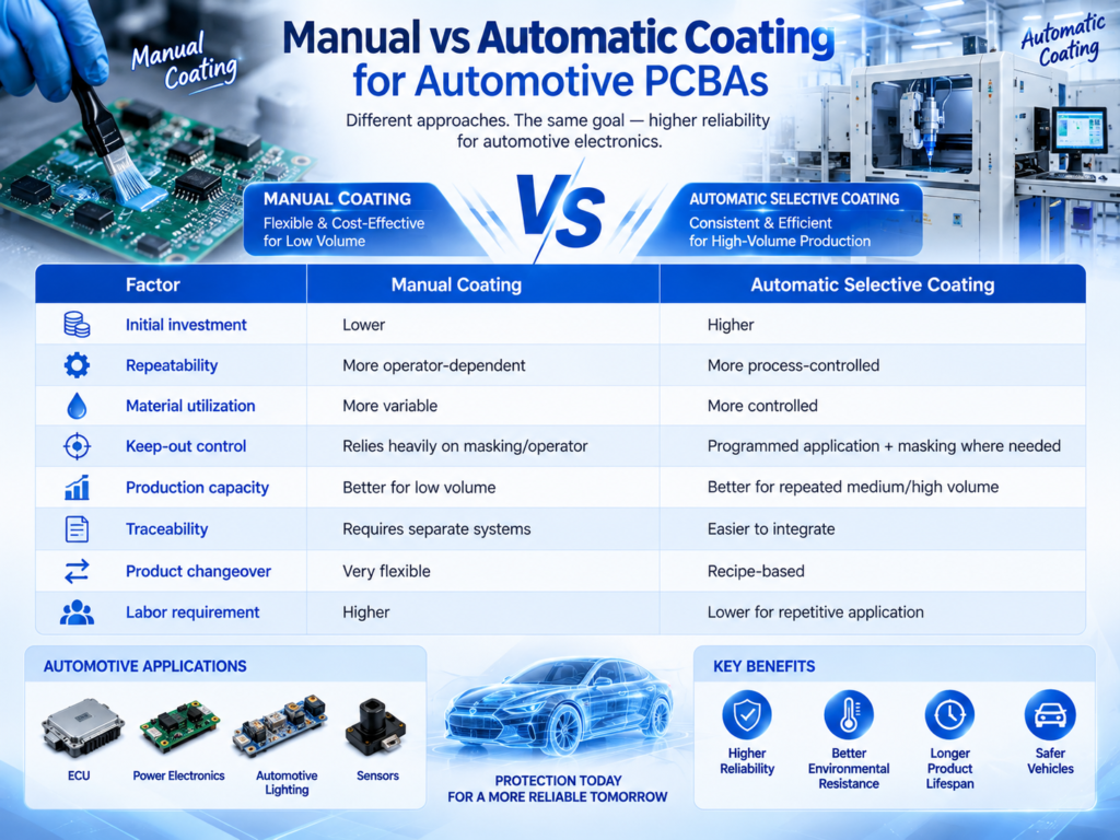
Manual vs Automatic Coating for Automotive PCBAs
Neither method is universally better.
Manual processes may remain suitable for prototypes and low-volume automotive products.
Automatic selective coating becomes more attractive when production volume and repeatability requirements increase.
Common Automotive PCBA Coating Defects
Dewetting
Dewetting occurs when coating pulls away from certain areas.
Potential causes can include:
- Oil
- Flux contamination
- Silicone contamination
- Poor surface cleanliness
- Bubbles
Possible causes include:
- Trapped air
- Excessive coating thickness
- Material handling
- Incorrect flash-off
- Surface conditions
- Pinholes
Potential factors include:
- Surface contamination
- Air release
- Material behavior
- Application parameters
- Overspray
Overspray may contaminate:
- Connectors
- Contacts
- Test points
- Switches
It can often be reduced through better:
- Program design
- Valve selection
- Masking
- Coating width control
- Pooling
Coating may accumulate around:
- Tall components
- Component bases
- Closely spaced structures
The coating path, flow rate, viscosity, and PCB geometry should be reviewed.
Uneven Coverage
Possible causes can include:
- Incorrect valve height
- Viscosity variation
- Unstable material pressure
- Incorrect speed
- Poor programming
- How to Improve Process Stability
Automotive coating processes benefit from disciplined process control.
Important areas include:
- PCB cleanliness
- Material storage
- Viscosity control
- Coating material condition
- Valve maintenance
- Correct flow rate
- Stable Z-height
- Recipe control
- Masking consistency
- Flash-off control
- Curing verification
- Inspection records
- Preventive maintenance
A stable process depends on the full chain from incoming PCBA condition through final cure.
Coating Line Traceability
Depending on product and customer requirements, manufacturers may need to record data such as:
- PCB serial number
- Production time
- Coating recipe
- Machine identification
- Operator
- Material batch
- Coating result
- Inspection result
- Curing process
- Final test result
The actual traceability architecture should be defined according to customer and factory requirements.
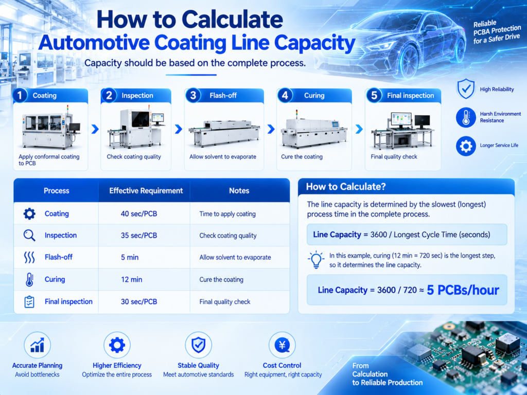
How to Calculate Automotive Coating Line Capacity
Capacity should be based on the complete process.
For example:
Long flash-off or curing times do not necessarily mean one board can be completed only every 12 minutes.
A conveyorized curing system can process multiple boards simultaneously.
Therefore, engineers should calculate:
- PCB spacing
- Conveyor speed
- Oven length
- Required residence time
- Buffer capacity
- Actual boards per hour
This is more useful than comparing only coating-machine cycle time.
How to Choose a Conformal Coating Machine for Automotive PCBA
Before selecting equipment, manufacturers should prepare:
- PCB dimensions
- PCB thickness
- Panel dimensions
- Component layout
- Maximum component height
- Coating areas
- Keep-out areas
- Coating chemistry
- Material viscosity
- Required application method
- Target coating thickness
- Target production capacity
- Product mix
- Changeover frequency
- Flash-off requirements
- Curing requirements
- Inspection requirements
- Traceability requirements
- Factory layout
- Existing equipment
- Automation level
- Investment budget
Representative PCB samples or layout information can also help evaluate valve access and process feasibility.
Factory Layout Considerations
Automotive PCBA coating lines should be planned with:
- Material preparation areas
- Masking stations
- Coating equipment
- Flash-off
- Curing
- Inspection
- Rework
- Exhaust
- Maintenance access
- WIP buffers
- Finished PCB flow
The coating line should also be balanced with upstream SMT/THT production.
Exhaust and Ventilation
Depending on the coating material, appropriate exhaust or ventilation may be required.
Manufacturers should review:
- Material safety data
- Solvent content
- Machine exhaust requirements
- Factory ventilation
- Local workplace and environmental requirements
This should be planned before machine installation.
Integrating Coating with an Automotive SMT Line
The coating process should be considered as part of the complete PCBA manufacturing flow.
A possible process is:
PCB Loading → Solder Paste Printing → SPI → SMT Placement → Reflow → AOI → THT Assembly → Wave/Selective Soldering → Inspection → Testing → Cleaning/Preparation → Conformal Coating → Curing → Final Inspection
If the SMT section produces significantly faster than coating and curing can process, WIP may accumulate.
Therefore, coating capacity should be considered during total factory line balancing.
New vs Pre-Owned Coating Equipment
Manufacturers can consider both new and suitable pre-owned equipment depending on requirements.
For pre-owned coating machines, check:
- Motion platform
- Coating valves
- Conveyor
- Pumps
- Material supply system
- Control software
- Exhaust interfaces
- Machine cleanliness
- Maintenance history
- Spare parts availability
- Technical support
For curing equipment, evaluate:
- Heating or UV system condition
- Conveyor stability
- Process controls
- Exhaust
- Compatibility with the intended coating material
Total cost of ownership should be considered rather than only initial purchase price.
Conformal Coating and PCBA Solutions from Fuliu Electronics
Established in 2014, Fuliu Electronics is dedicated to providing customers with high-quality PCBA intelligent manufacturing solutions and services.
With extensive experience in the SMT industry, we specialize in dependable equipment, professional technical support, and complete SMT and PCBA production line solutions.
Our product portfolio includes SMT pick and place machines from Fuji, Panasonic, ASM, Yamaha, JUKI, and Hanwha, together with ERSA reflow ovens from Germany, MagicRay SPI/AOI inspection systems, automatic solder paste printers, supporting PCBA equipment, pre-owned SMT equipment, SMT spare parts, machine leasing, and maintenance services.
For automotive electronics manufacturers planning a conformal coating process, Fuliu Electronics can help evaluate:
- PCB dimensions
- Component layout
- Coating areas
- Keep-out zones
- Coating materials
- Selective coating methods
- Target capacity
- Product mix
- Flash-off
- Curing
- Inspection
- Existing SMT/THT equipment
- Factory layout
- Automation requirements
- Investment budget
Rather than selecting coating equipment independently, manufacturers can plan SMT assembly, THT processing, testing, coating, curing, inspection, and material handling as one integrated PCBA production system.
As part of our global growth strategy, Fuliu Electronics is actively expanding into international markets, with key focus areas including India, Vietnam, the Philippines, Indonesia, the Middle East, South Africa, and Europe.
Frequently Asked Questions
No. The requirement depends on the module’s operating environment, product design, enclosure, customer specification, and reliability requirements.
Where appropriate, it can provide additional protection against moisture, humidity, condensation, dust, and certain environmental contaminants.
There is no universal best material. Acrylic, silicone, polyurethane, epoxy, UV-curable, and specialized coatings each have different characteristics. Selection should be based on the actual application.
Yes. It can provide repeatable, programmable application for medium- and high-volume production where PCB design and coating requirements are suitable.
Not always. Certain connectors, contacts, test points, and difficult geometries may still require masking.
It depends on the flux, coating material, surface cleanliness, and customer requirements. The cleaning process should be validated for the actual product.