
Wave soldering remains an important manufacturing process for through-hole PCB assembly, particularly when a PCB contains a large number of THT components.
Connectors, terminals, relays, transformers, switches, large capacitors, and selected power components are commonly assembled using Through-Hole Technology (THT). For high-volume production, wave soldering can provide an efficient method for creating multiple through-hole solder joints in a controlled process.
However, a wave soldering machine alone does not constitute a complete production line. A reliable wave soldering line configuration should coordinate PCB handling, flux application, preheating, soldering, cooling, inspection, and downstream testing.
This guide explains how to configure a wave soldering line, what equipment is required, how the process works, and what manufacturers should consider when planning a THT or DIP production line.
Wave Soldering Line Configuration for Through-Hole PCB Assembly
A wave soldering line is a production system designed to solder PCB assemblies by passing the board over one or more controlled waves of molten solder.
A typical process flow is:
PCB Loading → Fluxing → Preheating → Wave Soldering → Cooling → Inspection → Testing
In a complete DIP production line, additional processes may be placed before wave soldering, such as:
THT Component Preparation → DIP/THT Insertion → Insertion Inspection → Fluxing → Preheating → Wave Soldering
The final configuration depends on PCB design, component mix, production volume, and the relationship between SMT and THT processes.
Why Is Wave Soldering Important for THT Assembly?
Through-hole components have leads that pass through holes in the PCB. These leads need to be soldered to the corresponding pads to create reliable electrical and mechanical connections.
For high-volume manufacturing, manually soldering every through-hole joint can be time-consuming and inconsistent.
Wave soldering allows many suitable joints to be soldered during one continuous process.
Potential advantages include:
- High production efficiency
- Consistent soldering conditions
- Reduced manual soldering
- Suitable for high-volume THT production
- Repeatable process parameters
- Integration with automated PCB handling
However, wave soldering is not suitable for every PCB. Component arrangement, SMT components, PCB design, and soldering requirements must be considered before selecting the process.
What Equipment Is Needed for a Wave Soldering Line?
A complete wave soldering production line can include several pieces of equipment.
PCB Loader
A PCB loader transfers boards into the production line.
Depending on production requirements, loading can be manual, semi-automatic, or automatic.
The loader should support:
- PCB dimensions
- Board thickness
- Panel configuration
- Magazine specifications
- Conveyor direction
For automated production, compatibility with downstream conveyors is essential.
PCB Conveyor
Conveyors connect the individual stages of the wave soldering process.
A suitable conveyor system should provide stable PCB transportation and maintain consistent conveyor speed.
Important considerations include:
- PCB width
- Conveyor height
- Board orientation
- Transfer method
- Production speed
- Operator access
- Maintenance space
A poorly designed PCB handling system can become a bottleneck even when the wave soldering machine has sufficient capacity.
Fluxing System
Flux is typically applied before preheating and soldering.
Its purpose is to help remove oxides and promote solder wetting.
A modern wave soldering line may use a controlled spray fluxing system.
Key parameters include:
- Flux type
- Application volume
- Spray pattern
- Coverage
- Flux condition
- PCB speed
Consistent flux application is important for stable soldering results.
Excessive flux does not necessarily improve solder quality and may create downstream process problems.
Preheating System
After fluxing, the PCB passes through a preheating section.
Preheating gradually increases PCB temperature and supports appropriate flux activation before solder contact.
The required thermal profile depends on:
- PCB thickness
- Copper distribution
- PCB material
- Component thermal mass
- Flux characteristics
- Solder alloy
- Conveyor speed
The preheating system should therefore be selected based on the actual PCB requirements.
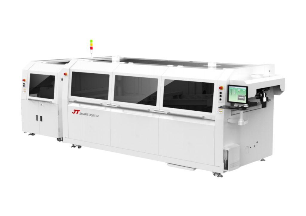
The wave soldering machine is the core equipment in the line.
During operation, the bottom side of the PCB comes into contact with molten solder.
The solder wets the exposed THT component leads and PCB pads, forming solder joints.
Important parameters include:
- Solder temperature
- Conveyor speed
- Wave height
- Contact time
- Flux application
- Preheating temperature
- Solder bath condition
- PCB angle
A stable process window should be established for each product.
Cooling System
After soldering, the PCB should be cooled under controlled conditions.
Cooling allows the solder joints to solidify before the board enters inspection or testing.
Cooling requirements depend on PCB construction, soldering conditions, and production requirements.
PCB Unloader
The unloader transfers finished boards from the wave soldering line to downstream inspection or production processes.
For automated production, PCB loading and unloading should be coordinated with the factory’s material flow.
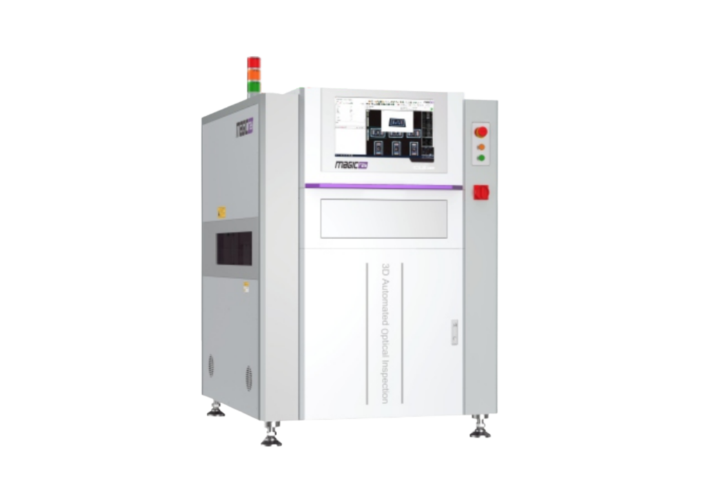
Inspection can be performed after soldering to identify potential defects.
Depending on the PCB and quality requirements, manufacturers may use:
- Visual inspection
- AOI
- Solder joint inspection
- X-ray inspection for selected applications
- Electrical testing
- Functional testing
Inspection should be integrated into the overall quality-control strategy.
Wave Soldering Process for Through-Hole PCB Assembly
A typical through-hole PCB assembly process using wave soldering can be divided into several stages.
Step 1: PCB and Component Preparation
PCBs and THT components are prepared according to the production BOM.
Components may require lead forming, cutting, sorting, or other preparation.
Step 2: THT Component Insertion
Through-hole components are inserted into the PCB manually, semi-automatically, or automatically.
Component polarity and orientation should be verified.
Step 3: Insertion Inspection
The board is checked for missing components, incorrect components, polarity problems, and insertion errors.
Step 4: Flux Application
Controlled flux is applied to the soldering area.
Step 5: Preheating
The PCB passes through the preheating section to prepare the assembly for soldering.
Step 6: Wave Soldering
The PCB passes through the solder wave, allowing molten solder to form joints between THT leads and PCB pads.
Step 7: Cooling
The PCB is cooled before inspection.
Step 8: Inspection and Testing
Solder joints and assembly quality are inspected before electrical or functional testing.
How to Configure the Wave Soldering Line
A suitable configuration should start with the product rather than the machine.
Analyze PCB Dimensions
Collect:
- PCB length
- PCB width
- PCB thickness
- Panel dimensions
- Board weight
- PCB material
- Component height
These specifications affect conveyor compatibility and machine configuration.
Analyze THT Components
Review the BOM and identify:
- Component types
- Lead lengths
- Lead spacing
- Component height
- Component density
- Large or heavy components
- Components requiring special soldering conditions
This information helps determine whether wave soldering is appropriate.
Define Production Capacity
Determine the required:
- Boards per hour
- Boards per shift
- Boards per day
- Monthly output
Actual capacity should consider changeovers, material replenishment, maintenance, and normal production downtime.
Determine Solder Alloy
The selected solder alloy influences the soldering process and equipment requirements.
Manufacturers should establish process parameters according to the selected alloy, flux, PCB, and components.
Determine Automation Level
A wave soldering line can be:
- Manual
- Semi-automatic
- Fully automated
High-volume factories may benefit from automated PCB handling, while high-mix manufacturers may prioritize flexibility.
Wave Soldering Line Layout
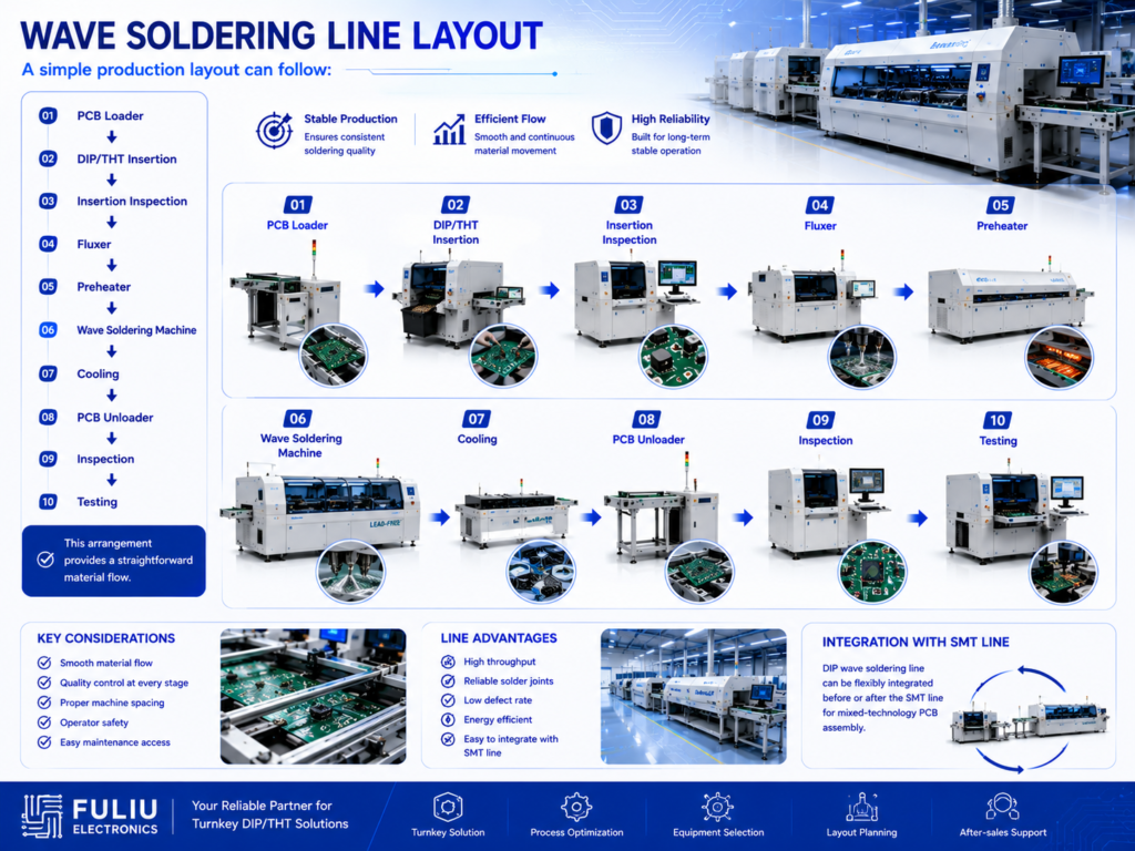
A simple production layout can follow:
PCB Loader
↓
DIP/THT Insertion
↓
Insertion Inspection
↓
Fluxer
↓
Preheater
↓
Wave Soldering Machine
↓
Cooling
↓
PCB Unloader
↓
Inspection
↓
Testing
This arrangement provides a straightforward material flow.
When designing the factory layout, manufacturers should also consider:
- Operator movement
- Component storage
- PCB buffer areas
- Equipment maintenance
- Exhaust and ventilation
- Electrical requirements
- Solder handling
- Safety
- Future expansion
The objective is to minimize unnecessary PCB movement while providing sufficient space for operation and maintenance.
Wave Soldering vs Selective Soldering
Wave soldering is not always the best choice for every THT PCB.
Wave Soldering
Wave soldering is often suitable when:
- Many THT joints need to be soldered
- Production volume is relatively high
- PCB design is compatible with wave soldering
- Continuous production is required
Selective Soldering
Selective soldering may be better when:
- Only certain THT joints need soldering
- SMT components are already assembled
- Some components cannot tolerate conventional wave soldering
- Localized soldering control is required
The choice should be based on PCB design, component placement, production volume, and process requirements.
Wave Soldering for Mixed SMT and THT PCB Assembly
Many modern PCB assemblies combine SMT and THT components.
A typical mixed-technology production process is:
Solder Paste Printing → SPI → SMT Placement → Reflow → AOI → THT/DIP Insertion → Fluxing → Wave/Selective Soldering → Inspection → Testing
SMT is generally used for compact surface-mounted components, while THT is often used for connectors, terminals, relays, transformers, switches, and selected power components.
This means a wave soldering line may operate as the downstream section of a complete SMT + DIP production line.
When planning a new PCBA factory, manufacturers should therefore consider the interaction between SMT and THT processes.
How to Improve Wave Soldering Quality
A stable wave soldering process depends on controlling multiple variables.
Control Solder Temperature
Solder temperature should remain within the appropriate process range for the selected alloy and PCB.
Control Conveyor Speed
Conveyor speed influences preheating, solder contact time, and overall process stability.
Maintain Proper Flux Application
Flux should be applied consistently and appropriately for the PCB and soldering process.
Optimize Preheating
Preheating should be developed according to PCB thickness, copper distribution, components, and flux requirements.
Monitor Wave Height
Wave height should remain stable and appropriate for the PCB design.
Maintain the Solder Bath
Solder contamination and process condition should be monitored according to the manufacturer’s process-control requirements.
Inspect Solder Joints
Appropriate visual inspection, AOI, X-ray, or electrical testing can help identify process problems.
Common Wave Soldering Defects
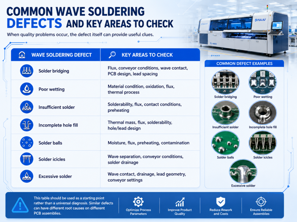
Manufacturers may encounter defects such as:
Solder Bridging
Excess solder connects adjacent pads or leads.
Possible contributing factors include PCB design, component spacing, solder wave conditions, flux, and conveyor settings.
Insufficient Solder
Not enough solder reaches the required joint area.
Potential causes include unsuitable wave conditions, insufficient fluxing, poor thermal preparation, or PCB design factors.
Poor Wetting
Solder does not properly spread over the required surfaces.
Flux condition, oxidation, thermal conditions, and solder parameters can influence wetting.
Incomplete Hole Fill
The solder does not adequately fill a through-hole.
PCB thickness, hole design, component lead configuration, preheating, fluxing, and soldering conditions can all influence hole fill.
Solder Icicles
Sharp projections of solidified solder may remain after wave soldering.
PCB design, solder wave conditions, conveyor settings, and solder drainage can contribute to this defect.
The correct solution should be determined through process analysis rather than changing one parameter without considering the complete system.
How to Choose a Wave Soldering Machine
Before purchasing a wave soldering machine, manufacturers should evaluate several factors.
PCB Size
Verify that the machine supports the actual board and panel dimensions.
Production Volume
Select a machine with suitable throughput for the target production level.
Fluxing System
Check flux application accuracy, control, and maintenance requirements.
Preheating Capacity
Ensure the preheating system can achieve the required thermal profile.
Wave Configuration
Evaluate whether the wave system is appropriate for the PCB design and soldering requirements.
Solder Alloy
Confirm compatibility with the selected solder alloy.
Maintenance
Consider accessibility, cleaning requirements, consumables, spare parts, and technical support.
Factory Utilities
Review power, exhaust, ventilation, compressed air, and other requirements before installation.
How to Configure the Line Based on Production Volume
Low-Volume / High-Mix Production
A suitable configuration may prioritize:
- Manual THT insertion
- Flexible PCB handling
- Manual inspection
- Automated wave or selective soldering
Flexibility is often more important than maximum automation.
Medium-Volume Production
A semi-automated line may combine:
- Automated PCB handling
- Manual or semi-automatic insertion
- Automatic fluxing
- Preheating
- Wave soldering
- Inspection
This can balance productivity and investment.
High-Volume Production
A high-volume line may include:
- Automatic PCB loading
- Automatic THT insertion
- Automated PCB transfer
- High-capacity wave soldering
- Automated inspection
- Traceability systems
The appropriate configuration should be based on actual utilization and expected return on investment.
How Fuliu Electronics Supports PCBA Production Line Solutions
Established in 2014, Fuliu Electronics is dedicated to providing customers with high-quality PCBA intelligent manufacturing solutions and services.
With extensive experience in the SMT industry, we specialize in dependable equipment, professional technical support, and complete solutions for SMT, DIP/THT, and PCBA production lines.
Our product portfolio includes SMT pick and place machines from Fuji, Panasonic, ASM, Yamaha, JUKI, and Hanwha, along with ERSA reflow ovens from Germany, MagicRay SPI/AOI inspection systems, automatic solder paste printers, supporting SMT equipment, pre-owned SMT equipment, SMT spare parts, machine leasing, and maintenance services.
For manufacturers planning a wave soldering line for through-hole PCB assembly, Fuliu Electronics can help evaluate:
- PCB dimensions
- THT component types
- BOM information
- Production capacity
- Wave or selective soldering requirements
- Existing SMT equipment
- Factory layout
- Automation requirements
- New or pre-owned equipment options
- Maintenance and spare parts requirements
For factories operating both SMT and THT processes, the wave soldering process can be planned as part of a complete SMT + DIP PCBA production solution.
As part of our global growth strategy, Fuliu Electronics is actively expanding into international markets, with key focus areas including India, Vietnam, the Philippines, Indonesia, the Middle East, South Africa, and Europe.
Conclusion
A successful wave soldering line configuration for through-hole PCB assembly requires careful coordination of equipment, process parameters, factory layout, and production requirements.
The key elements include:
- PCB handling
- THT/DIP insertion
- Flux application
- Preheating
- Wave or selective soldering
- Cooling
- Inspection
- Testing
- Maintenance
- Future capacity planning
For high-volume THT production, wave soldering can provide an efficient and repeatable soldering solution. For mixed SMT and THT products, it can also serve as an important downstream process within a complete PCBA production line.
The best configuration should always be based on the actual PCB, BOM, component types, production capacity, product mix, and factory conditions.
If you are planning a wave soldering line, DIP production line, or complete SMT + THT PCBA solution, Fuliu Electronics can help evaluate your PCB specifications, BOM, production capacity, factory layout, existing equipment, and automation requirements to develop a suitable production line configuration.
Frequently Asked Questions
A wave soldering line is a production system used to solder PCB assemblies by passing the board over molten solder. A complete line may include PCB handling, fluxing, preheating, wave soldering, cooling, inspection, and testing.
A typical line includes a PCB loader, conveyors, fluxing system, preheater, wave soldering machine, cooling section, PCB unloader, and inspection equipment.
If used as part of a DIP line, THT insertion equipment may also be required.
Yes. Wave soldering is widely used for high-volume through-hole PCB assembly because multiple suitable THT joints can be soldered in a continuous process.
Wave soldering exposes a larger area of the PCB underside to molten solder, while selective soldering applies solder to specific through-hole locations.
The best process depends on PCB design, component arrangement, and production requirements.
Yes. Many mixed-technology PCB assemblies use SMT reflow first and then THT insertion followed by wave or selective soldering.
The process sequence should be determined by PCB design and component requirements.
Potential contributing factors include solder temperature, conveyor speed, flux application, preheating, wave height, PCB design, component condition, solder bath condition, and equipment maintenance.
Defect analysis should consider the complete process rather than changing one parameter in isolation.