
LED drivers are an important category of power electronics used in lighting systems, industrial equipment, commercial lighting, automotive applications, and other electronic products.
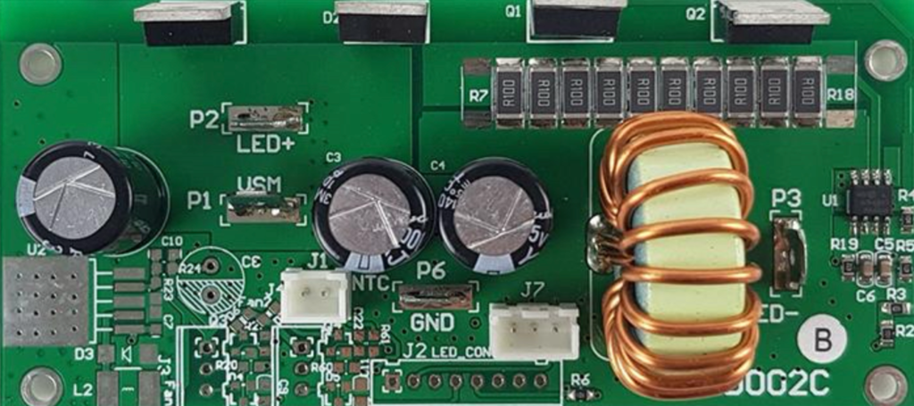
Unlike simple control boards, many LED driver PCBs combine SMT control components with power-related and high-thermal-mass components. Depending on the product design, the PCB may contain ICs, resistors, capacitors, diodes, MOSFETs, inductors, transformers, connectors, fuses, and other components.
This creates several manufacturing challenges:
- Different component sizes and package types
- Large copper areas and high thermal mass
- High-density SMT placement
- Polarity and orientation requirements
- Heat-sensitive components
- Potentially heavy components
- Functional and electrical testing requirements
- Different PCB models and production volumes
Therefore, an SMT line configuration for LED driver manufacturing should be based on the actual PCB, BOM, production capacity, component mix, testing requirements, and factory conditions rather than simply selecting machines by rated placement speed.
Typical SMT Process for LED Driver PCB Assembly
A typical LED driver PCB assembly process may include:
PCB Loading → Solder Paste Printing → SPI → Pick and Place → Reflow Soldering → AOI → Testing → PCB Unloading
For products containing significant through-hole components, the process may be expanded:
SMT Printing → SPI → SMT Placement → Reflow → AOI → THT/DIP Insertion → Wave or Selective Soldering → Inspection → Functional Testing
Additional processes may include:
- X-ray inspection
- Programming
- Electrical testing
- Burn-in testing
- Conformal coating
- Cleaning
- Barcode identification
- Traceability
- Automated handling
- Rework
The correct configuration depends on the LED driver design and customer requirements.
Start with PCB and BOM Analysis
Before selecting SMT equipment, manufacturers should analyze the actual product.
Important information includes:
- PCB Information
- PCB length and width
- Thickness
- Weight
- Panel dimensions
- Number of boards per panel
- PCB material
- Copper distribution
- Warpage considerations
- BOM Information
- Total component quantity
- Smallest package
- Largest component
- Component height
- IC packages
- Power semiconductors
- Inductors and transformers
- Electrolytic capacitors
- Connectors
- THT components
- Polarity-sensitive components
- Production Information
- Monthly production volume
- Target boards per hour
- Product mix
- Number of PCB models
- Working shifts
- Expected future capacity
This information determines the required printer size, SPI capability, placement machine configuration, feeder capacity, reflow oven zones, AOI coverage, and testing capacity.
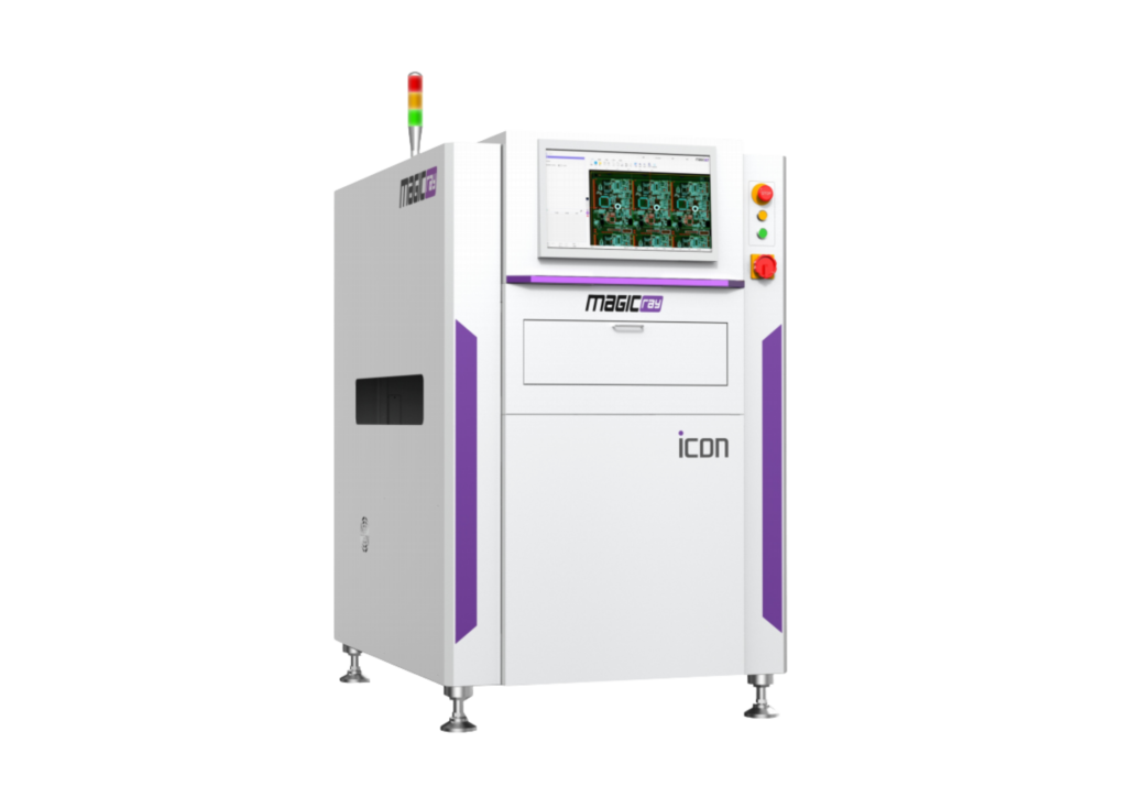
Automatic Solder Paste Printer and SPI
Automatic Solder Paste Printer
For medium- and high-volume LED driver production, an automatic solder paste printer is generally preferred because printing consistency directly affects downstream soldering quality.
Important considerations include:
- PCB size range
- Stencil dimensions
- Automatic alignment
- Support tooling
- Squeegee configuration
- Paste separation performance
- Stencil cleaning
- Board thickness
- Printing cycle time
Large copper areas and thermal pads may require careful stencil design and support to achieve consistent solder paste deposition.
SPI Inspection
SPI can inspect solder paste deposition before component placement.
Typical inspection parameters include:
- Paste volume
- Paste height
- Paste area
- Position
- Shape
SPI is especially useful when the PCB contains fine-pitch ICs, thermal pads, or densely populated areas.
An important advantage is that printing problems can be detected before components are placed, reducing the cost of discovering defects later in the process.
Selecting Pick and Place Machines
The placement system is one of the most important parts of an LED driver SMT line.
A suitable configuration should consider:
- Placement speed
- Placement accuracy
- Component range
- Feeder capacity
- Tray support
- Component recognition
- PCB dimensions
- Component height
- Product changeover requirements
LED driver boards may contain both small passive components and relatively large power-related components. A flexible placement machine can therefore be more practical than selecting equipment purely according to maximum chip placement speed.
Example Capacity Calculation
Suppose a PCB requires: 350 component placements
Target production rate: 120 boards/hour
The theoretical placement requirement is: 350 × 120 = 42,000 placements/hour
However, the required machine capacity should not be based only on this calculation.
Actual throughput can be affected by:
- Component distribution
- Feeder arrangement
- Component recognition
- Nozzle changes
- Tray components
- PCB transfer time
- Machine configuration
- Product changeover
- Equipment utilization
Therefore, manufacturers should evaluate actual production conditions rather than relying only on the headline placement speed.
Reflow Oven Configuration for LED Driver PCBs
Reflow soldering is particularly important for LED driver manufacturing because power-related components and large copper areas can create different thermal requirements across the PCB.
A reflow oven should provide sufficient thermal control and process stability for the actual product.
Key considerations include:
- Number of heating zones
- Cooling zones
- Conveyor width
- Maximum PCB height
- Thermal uniformity
- Temperature control
- Recipe management
- Nitrogen capability where required
There is no universal reflow profile for every LED driver PCB.
The profile should be developed based on factors such as:
- Solder paste specification
- PCB thickness
- Copper distribution
- Component thermal mass
- Component temperature limits
- Board design
- Production requirements
Thermal profiling should therefore be performed using the actual PCB and production materials.
AOI and X-Ray Inspection
After reflow, AOI can detect many visible assembly defects, including:
- Missing components
- Incorrect placement
- Component shift
- Polarity errors
- Solder bridges
- Insufficient visible solder
- Incorrect component orientation
For selected packages with hidden solder joints, such as certain BGA or QFN designs, X-ray inspection may provide additional information.
However, X-ray is not automatically required for every LED driver PCB. Its necessity depends on the actual component packages, customer requirements, quality strategy, and process risk.
AOI and X-ray also do not replace electrical or functional testing.
Testing Is Critical for LED Driver Manufacturing
Testing can become a major bottleneck in LED driver production.
Depending on the product architecture, testing may include:
- Continuity testing
- ICT
- Programming
- Functional testing
- Output voltage testing
- Output current testing
- Communication testing
- Dimming control verification
- Protection-function testing
- Product-specific electrical testing
Safety or high-voltage testing may also be required depending on the product design, applicable requirements, and customer specifications.
For example, consider a simplified production line:
The practical line capacity cannot be assumed to be 180 boards/hour. If functional testing is the bottleneck, the overall production flow may be constrained toward the testing capacity.
This is why line balancing should include downstream testing, not only SMT equipment.
SMT Line Configuration Examples
Configuration A: High-Mix LED Driver Production
A flexible configuration could include:
PCB Loader → Automatic Printer → SPI → Flexible Placement Machine → Reflow Oven → AOI → Programming → Functional Testing → Unloader
This configuration is suitable when manufacturers produce multiple LED driver models with different BOMs.
The focus should be on:
- Flexible feeders
- Fast changeover
- Recipe management
- Offline setup
- Barcode management
- Flexible placement capability
Configuration B: Medium-Volume Production
A medium-volume line may use:
PCB Loader → Automatic Printer → SPI → High-Speed/Flexible Placement → Reflow → AOI → Testing → PCB Unloader
The exact number and combination of placement machines should be determined by placement requirements and target capacity.
Configuration C: High-Volume LED Driver Manufacturing
For high-volume production, manufacturers may consider:
Automatic Loading → Printing → SPI → Multiple Placement Machines → Reflow → AOI → Parallel Testing → Automatic Unloading
Parallel testing can be particularly useful when electrical or functional testing requires a relatively long cycle time.
For example, if one test station requires 60 seconds per board while the production takt is approximately 20 seconds, multiple test positions may be required to prevent testing from becoming the bottleneck.
Wave or Selective Soldering for LED Driver PCBs
Some LED driver designs include THT components such as:
- Transformers
- Inductors
- Terminal blocks
- Connectors
- Large capacitors
- Relays
- Fuses
- Selected power components
In these cases, an SMT process may need to be combined with THT assembly.
Wave soldering can be suitable when many compatible THT joints can be processed together.
Selective soldering can be more appropriate when only specific THT joints require soldering, especially when the PCB contains bottom-side SMT components or localized soldering requirements.
The choice should be based on PCB layout, THT joint distribution, production volume, soldering accessibility, and product mix.
Line Balancing and Factory Layout
A complete SMT line should not be designed as a collection of independent machines.
Manufacturers should consider:
- PCB flow direction
- Buffer capacity
- Material feeding
- Feeder preparation
- Operator access
- Rework area
- Inspection stations
- Testing area
- Finished PCB handling
- ESD control
- Compressed air
- Electrical power
- Exhaust
- Nitrogen, if required
- Maintenance access
For high-mix manufacturing, feeder preparation and material kitting can have a significant impact on changeover time.
A production line with high machine capacity can still perform poorly if material preparation, testing, rework, or manual handling becomes a bottleneck.
Traceability and Production Data
For LED driver manufacturing, traceability can be designed according to product and customer requirements.
A traceability system may associate:
- PCB serial number
- Product model
- PCB revision
- Production time
- Machine information
- Program version
- Material or component lot
- Solder paste information
- SPI results
- Reflow profile data
- AOI results
- Programming results
- Functional test results
This can help manufacturers investigate quality issues and identify process trends.
Recipe and program revision management are also important when multiple LED driver models are produced on the same SMT line.
Should You Buy New or Pre-Owned SMT Equipment?
Both new and pre-owned SMT equipment can be considered depending on the project.
New Equipment
New machines may be attractive when the factory requires:
- New production capacity
- Modern automation
- Standardized equipment
- New software functions
- Long-term production planning
Pre-Owned Equipment
Pre-owned equipment can help control initial investment when its actual condition and production capability are suitable.
Important evaluation points include:
- Equipment condition
- Placement accuracy
- Operating hours
- Feeder condition
- Software availability
- Spare parts
- Maintenance history
- Calibration or verification
- Technical support
- Machine compatibility
A hybrid SMT line combining new and pre-owned equipment may also be considered when the goal is to balance investment and production capability.
Why Choose Fuliu Electronics for LED Driver SMT Line Planning?
Established in 2014, Fuliu Electronics focuses on providing high-quality PCBA intelligent manufacturing solutions and services.
With extensive SMT industry experience, Fuliu Electronics provides:
- SMT production line planning
- Pick and place machines
- Automatic solder paste printers
- ERSA reflow ovens from Germany
- MagicRay SPI and AOI inspection systems
- SMT equipment leasing
- SMT equipment maintenance
- Pre-owned SMT equipment
- SMT spare parts
- Complete SMT production line solutions
Fuliu Electronics works with equipment from major brands including Fuji, Panasonic, ASM, Yamaha, JUKI, and Hanwha, allowing different equipment combinations to be considered according to PCB characteristics, production volume, automation requirements, and investment plans.
For LED driver manufacturers, the objective is not simply to supply individual machines, but to develop a production configuration that considers printing, placement, reflow, inspection, testing, material flow, capacity, and future expansion as one system.
Fuliu Electronics is also developing international markets across India, Vietnam, the Philippines, Indonesia, the Middle East, South Africa, and Europe.

Frequently Asked Questions
A typical line includes an automatic solder paste printer, SPI, pick and place machine, reflow oven, AOI, PCB handling equipment, and downstream testing. THT equipment may be added when required.
Start with PCB dimensions, BOM, component range, placement quantity, target capacity, and product mix. Machine selection should be based on actual production requirements rather than placement speed alone.
SPI is not mandatory for every factory, but it can provide valuable early detection of solder paste printing problems and improve process control, particularly for higher-volume or higher-density production.
The oven should provide sufficient thermal capacity and temperature control for the actual PCB, solder paste, and component mix. The required configuration should be confirmed through thermal profiling.
AOI can help detect many visible assembly defects after reflow. Whether it is required depends on production volume, product risk, quality requirements, and inspection strategy.
Not necessarily. X-ray is mainly useful when the PCB contains hidden solder joints or other structures that cannot be adequately inspected by conventional optical inspection.