
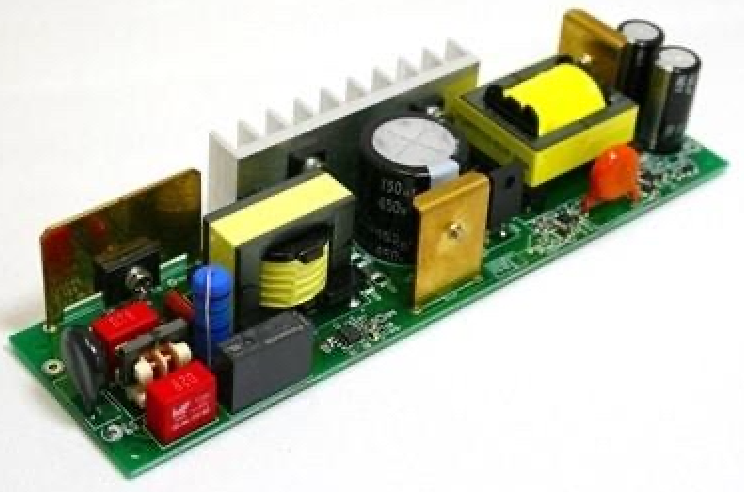
LED drivers are used to regulate and deliver electrical power to LED lighting systems. Depending on product design, an LED driver PCBA may combine compact SMT electronics with larger power, magnetic, and connection components.
This creates a manufacturing process that can require both SMT and through-hole assembly.
Typical components may include:
- SMT resistors and capacitors
- Control ICs
- Diodes
- MOSFETs and other semiconductor devices
- Transformers
- Inductors
- Electrolytic capacitors
- Connectors
- Terminal blocks
- Fuses
- Selected power resistors
For these products, building an efficient DIP production line for LED driver manufacturing requires more than installing a wave soldering machine.
The complete process should be considered:
SMT Assembly → THT Component Preparation → DIP/THT Insertion → Pre-Solder Inspection → Wave or Selective Soldering → Cooling → Inspection → Testing
The correct line configuration depends on the PCB design, BOM, component packaging, production volume, product mix, soldering requirements, testing strategy, factory layout, and automation target.
What Is a DIP Production Line?
In electronics manufacturing, a DIP production line generally refers to the production section used for through-hole component insertion and soldering.
A typical process is:
PCB Loading → Component Preparation → THT Insertion → Inspection → Fluxing → Preheating → Soldering → Cooling → Inspection → Testing
The term “DIP line” is commonly used in factories, although THT production line is technically broader.
DIP vs THT: What Is the Difference?
DIP means Dual In-line Package, a component package with two parallel rows of leads.
THT means Through-Hole Technology, a mounting method where component leads are inserted through holes in the PCB.
Therefore:
DIP is a package type, while THT is a mounting technology.
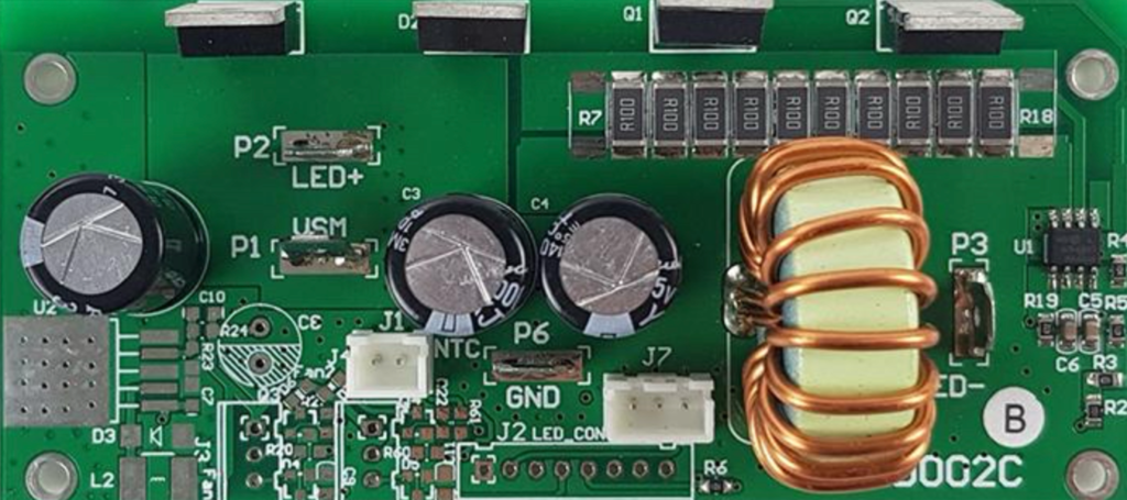
An LED driver may contain transformers, capacitors, inductors, connectors, and terminals that use through-hole mounting but are not DIP packages.
Nevertheless, “DIP production line” remains common industry terminology for this type of assembly process.
Why Do LED Driver PCBAs Use THT Components?
Modern LED driver PCBAs can use a high percentage of SMT components, but through-hole components remain useful where the product design calls for component structures not suited to conventional SMT placement.
Depending on the driver design, THT parts may include:
- Transformers
- Common-mode chokes
- Inductors
- Large electrolytic capacitors
- Connectors
- Terminal blocks
- Fuses
- Power resistors
- Selected semiconductor packages
Some of these components are physically larger or have irregular geometries.
Others may use through-hole mounting because of the component package or mechanical/electrical design.
The exact structure varies by LED driver, so manufacturers should review the actual BOM before configuring the production line.
Typical LED Driver PCBA Manufacturing Process
A mixed SMT + THT LED driver production process may be:
PCB Loader → Solder Paste Printing → SPI → SMT Placement → Reflow → AOI → THT Component Preparation → THT Insertion → Pre-Solder Inspection → Wave/Selective Soldering → Cooling → Inspection → Testing
Additional downstream processes may include:
- Programming where applicable
- Conformal coating where required
- Mechanical assembly
- Final product testing
The exact sequence should follow the actual product and process requirements.
Step 1: SMT Assembly
The SMT section can process components such as:
- Chip resistors
- Ceramic capacitors
- Small diodes
- ICs
- Transistors
- Driver/control components
- Selected power semiconductors
A typical SMT line includes:
PCB Loader → Automatic Solder Paste Printer → SPI → Pick and Place Machine(s) → Reflow Oven → AOI → PCB Unloader/Buffer
SMT equipment should be selected based on:
- PCB dimensions
- Component range
- BOM
- Placement quantity
- Product mix
- Target capacity
Nominal placement speed alone should not determine line configuration.
Step 2: THT Component Preparation
LED driver production may require preparation of through-hole components before insertion.
Processes can include:
- Lead cutting
- Lead forming
- Bending
- Straightening
- Component sorting
- Kitting
For high-volume production, repetitive component preparation can become a significant labor requirement.
Manufacturers should identify which preparation operations can be automated or semi-automated.
Step 3: Classify THT Components
Before purchasing automatic insertion equipment, classify the THT BOM.
Automatic Insertion Candidates
Automation may be practical when components have:
- Standardized geometry
- Consistent leads
- Compatible packaging
- Controlled orientation
- Sufficient production volume
- Semi-Automatic Candidates
Semi-automatic workstations can help with:
- Component presentation
- Visual guidance
- PCB positioning
- Material verification
- Manual Insertion Candidates
Manual insertion may remain practical for:
- Transformers
- Large inductors
- Large capacitors
- Irregular connectors
- Terminal blocks
- Low-quantity components
A hybrid production line can often provide a better balance between flexibility and automation.
Step 4: Design the THT Insertion Workstations
For components that remain manual, workstation design directly affects production efficiency.
A practical insertion area can include:
- ESD workbench
- Conveyor
- Component racks
- Clearly identified material bins
- Fixtures
- Lighting
- Work instructions
Components should be arranged according to insertion sequence where practical.
This can reduce unnecessary operator movement and component-search time.
Preventing Polarity and Orientation Errors
LED driver PCBAs may contain polarized components such as electrolytic capacitors and diodes.
Incorrect installation can create downstream quality problems.
Potential controls include:
- Clear PCB markings
- Component-bin identification
- Visual work instructions
- Material verification
- Guided workstations
- Pre-solder inspection
Errors should ideally be detected before soldering, when correction is easier.
Step 5: Pre-Solder Inspection
Before the PCB enters the soldering process, inspect for:
- Missing components
- Wrong components
- Incorrect polarity
- Incorrect orientation
- Bent leads
- Incorrect insertion depth
- Poor component seating
For high-volume production, early detection is particularly important because repeated assembly errors can quickly affect a large batch.
Step 6: Choose Wave or Selective Soldering
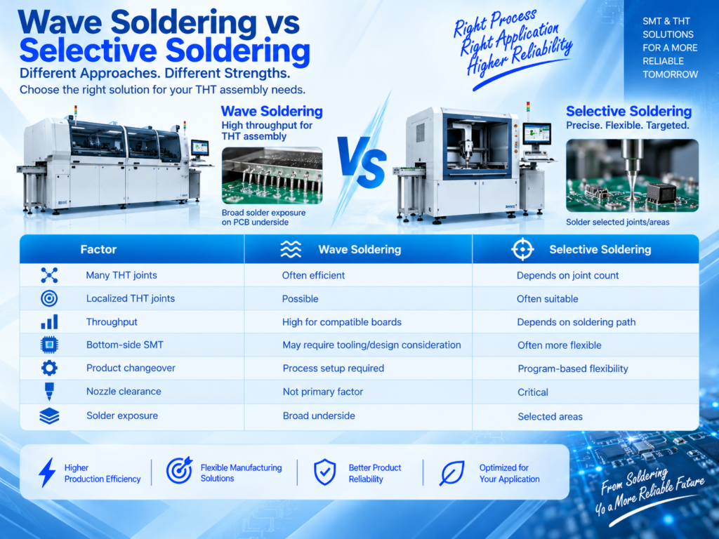
Two common automated THT soldering processes are:
- Wave Soldering and Selective Soldering.
- The decision should be based on:
- Number of THT joints
- PCB underside layout
- Bottom-side SMT components
- Component spacing
- Product mix
- Required throughput
- Tooling requirements
Wave Soldering for LED Driver PCB Assembly
Wave soldering can be efficient for LED driver boards containing many compatible through-hole joints.
A typical process includes:
Fluxing → Preheating → Wave Soldering → Cooling
Wave soldering equipment can include:
- Spray fluxer
- Preheat zones
- Conveyor
- Solder pot
- Pump/wave system
- Cooling
- Control system
Important process variables include:
- Flux application
- Preheat
- Solder temperature
- Conveyor speed
- Wave stability
- PCB orientation
- Lead condition
- Equipment maintenance
There is no universal wave soldering recipe for every LED driver PCB.
Selective Soldering for LED Driver PCBA
Selective soldering targets specific THT joints using a programmed process.
It may be useful when:
- Only selected through-hole joints require soldering
- Bottom-side SMT components restrict wave contact
- The PCB has localized THT areas
- Certain areas should avoid broad solder exposure
- Product mix requires flexible programming
A typical selective soldering process includes:
Selective Fluxing → Preheating → Programmed Soldering → Cooling
Nozzle accessibility and bottom-side clearance should be evaluated using the actual PCB.
Wave Soldering vs Selective Soldering
Neither process is universally better.
Different LED driver models in the same factory may use different soldering strategies.
PCB Thermal Characteristics Matter
LED driver PCBAs are power-electronics products, and some designs may include:
- Larger copper areas
- Higher thermal-mass components
- Power devices
- Transformers
- Inductors
- Large connectors
These features can affect the soldering process.
For example, a high-thermal-mass joint may heat differently from a small signal joint.
Manufacturers should therefore validate actual PCB thermal behavior rather than relying only on equipment setpoints.
Why Preheating Matters
Preheating can support:
- Flux activation
- Gradual PCB heating
- Reduced thermal differences
- Solder wetting
Insufficient preheating can contribute to soldering problems, particularly where thermal mass is significant.
However, excessive heating can also create risks.
The correct profile depends on the PCB, flux, solder alloy, components, and equipment.
PCB Orientation in Wave Soldering
PCB orientation can influence solder drainage and bridging behavior.
During process development, manufacturers should consider:
- Component direction
- Lead arrangement
- Pad geometry
- Connector orientation
- Board travel direction
The optimum orientation should be validated using the actual PCB.
Does an LED Driver PCB Need a Wave Soldering Pallet?
Not necessarily.
A pallet may be useful to:
- Support the PCB
- Shield selected areas
- Protect bottom-side components
- Control solder exposure
However, pallets add:
- Tooling cost
- Thermal mass
- Cleaning
- Maintenance
- Storage
Use them where the PCB design and soldering process justify the additional tooling.
Step 7: Cooling
After soldering, the PCB should cool sufficiently before downstream handling and inspection.
Cooling can be:
- Integrated into the soldering machine
- Added through a separate cooling conveyor
For continuous production, cooling capacity should be matched to line throughput.
Step 8: Post-Solder Inspection
Common THT soldering defects can include:
- Solder bridges
- Insufficient solder
- Poor wetting
- Incomplete hole fill
- Excessive solder
- Icicles
- Solder balls
Possible causes include:
- Flux application
- Preheat
- Solderability
- Solder temperature
- Conveyor parameters
- PCB design
- Lead condition
- Equipment maintenance
Troubleshooting should consider the complete process rather than adjusting only one parameter.
Step 9: Electrical and Functional Testing
Testing is an important part of LED driver PCBA manufacturing.
Depending on the product and production strategy, testing can include:
- ICT
- Continuity checks
- Programming
- Functional testing
- Product-specific electrical testing
Testing involving higher voltages or other safety-related conditions should use appropriate equipment and procedures according to the actual product requirements and applicable standards.
Testing capacity should also be included in line balancing.
Testing Can Become the Bottleneck
Consider a production line with:
Even though the wave soldering machine can process 110 boards per hour, finished output is approximately limited to 45 boards per hour by testing.
Buying a faster soldering machine would not solve the real bottleneck.
Line Balancing for LED Driver Manufacturing
Evaluate the complete flow:
Component Preparation → THT Insertion → Inspection → Soldering → Inspection → Testing
Important production metrics include:
- Takt time
- Cycle time
- WIP
- First-pass yield
- Rework
- Changeover time
- Equipment downtime
The goal is to increase good finished PCBAs rather than maximize the speed of a single process.
How Many THT Operators Are Required?
Suppose total manual insertion work is:
- 180 seconds per PCB
- The required takt is:
- 45 seconds per PCB
A simplified calculation is:
180 ÷ 45 = 4 operator-equivalent stations
Approximately four balanced insertion stations may therefore be required before allowances for:
- Material replenishment
- Operator efficiency
- Product variation
- Breaks
- Changeover
Actual production data should be used to validate staffing.
High-Mix LED Driver Production Line
For factories producing multiple LED driver models, a flexible configuration may be:
Component Preparation → Manual/Semi-Automatic THT Insertion → Pre-Solder Inspection → Wave/Selective Soldering → Inspection → Testing
Priorities include:
- Flexible workstations
- Fast material changeover
- Recipe management
- Adjustable conveyors
- Flexible soldering
- Standardized work instructions
In high-mix production, fast changeover can be more valuable than maximum equipment speed.
Medium-Volume LED Driver DIP Line
A practical medium-volume configuration may include:
Automatic PCB Loading → Component Preparation → Insertion Conveyor → Manual/Semi-Automatic THT Insertion → Pre-Solder Inspection → Wave Soldering → Cooling → Inspection → Parallel Testing
This configuration balances:
- Labor
- Flexibility
- Investment
- Throughput
High-Volume Automatic LED Driver DIP Line
For stable, higher-volume production, manufacturers may evaluate:
Automatic PCB Loading → Automatic Component Preparation → Automatic THT Insertion for Suitable Components → Manual Insertion for Irregular Parts → Automatic Transfer → Wave/Selective Soldering → Cooling → Inspection → Parallel Testing → Automatic Unloading
Optional functions can include:
- Barcode identification
- Automatic conveyor width adjustment
- Buffers
- Recipe management
- Traceability
- Production-data collection
Automation should be justified by actual production requirements.
Material Logistics for High-Volume Production
Production equipment cannot maintain high utilization without reliable material supply.
Plan:
- Incoming component storage
- Kitting
- Component preparation
- Line-side material
- Material verification
- Replenishment
- Empty packaging removal
Poor material logistics can stop a fast automatic production line.
Integrating SMT and DIP Production
A complete LED driver PCBA factory may use:
Solder Paste Printing → SPI → SMT Placement → Reflow → AOI → THT Insertion → Wave/Selective Soldering → Inspection → Testing
SMT and DIP capacities should be balanced.
For example:
- SMT output: 120 boards/hour
- DIP/THT output: 65 boards/hour
If both processes operate continuously without scheduling or buffers, WIP will accumulate before THT assembly.
Possible solutions include:
- Parallel insertion stations
- Component-preparation automation
- Partial automatic insertion
- Better production scheduling
- Controlled buffers
Should LED Driver PCBAs Use Conformal Coating?
Some LED driver products may use conformal coating depending on:
- Operating environment
- Product design
- Enclosure
- Customer specification
A possible downstream process is:
Testing → Cleaning/Surface Preparation → Selective Coating → Inspection → Flash-Off → Curing → Final Inspection
However, conformal coating is not universally required for every LED driver PCBA.
The coating decision should be based on actual product requirements.
Traceability for LED Driver Manufacturing
Depending on customer and production requirements, manufacturers may record:
- PCB serial number
- Production time
- Product model
- Machine
- Material lot
- Soldering recipe
- Inspection result
- Test result
Barcode integration can connect PCB identification with production data.
The required level of traceability should be defined before equipment selection.
Factory Layout for an LED Driver DIP Line
A practical layout should consider:
- Component storage
- Component preparation
- THT insertion
- Pre-solder inspection
- Soldering
- Cooling
- Post-solder inspection
- Testing
- Rework
- Downstream assembly
Material should move logically through the factory.
Avoid unnecessary:
- Backtracking
- Long-distance transport
- Cross-traffic
- Repeated handling
- Utilities and Exhaust
Depending on equipment configuration, the DIP line may require:
- Electrical power
- Compressed air
- Exhaust
- Ventilation
Nitrogen where required by the process
Network connection for production systems
Utility requirements should be confirmed before equipment installation.
Preventive Maintenance
Stable high-volume production requires planned maintenance.
For wave soldering equipment, important areas can include:
- Fluxing system
- Preheaters
- Conveyor
- Solder pot
- Pump/wave
- Cooling
- Exhaust
- Controls
For insertion equipment, review:
- Feeders
- Sensors
- Insertion mechanisms
- PCB transport
- Controls
Preventive maintenance should follow equipment requirements and actual utilization.
New vs Pre-Owned DIP Equipment
LED driver manufacturers can evaluate both new and suitable pre-owned equipment.
Pre-owned equipment may help reduce initial investment, but inspect:
- Mechanical condition
- Conveyor
- Feeding system
- Fluxer
- Preheaters
- Solder pot
- Wave/nozzle system
- Controls
- Software
- Maintenance history
- Spare-parts availability
Total cost of ownership should be considered rather than purchase price alone.
DIP Production Line Solutions from Fuliu Electronics
Established in 2014, Fuliu Electronics is dedicated to providing customers with high-quality PCBA intelligent manufacturing solutions and services.
With extensive experience in the SMT industry, we specialize in dependable equipment, professional technical support, and complete SMT and PCBA production line solutions.
Our product portfolio includes SMT pick and place machines from Fuji, Panasonic, ASM, Yamaha, JUKI, and Hanwha, together with ERSA reflow ovens from Germany, MagicRay SPI/AOI inspection systems, automatic solder paste printers, supporting PCBA equipment, pre-owned SMT equipment, SMT spare parts, machine leasing, and maintenance services.
Rather than selecting individual machines independently, manufacturers can evaluate the complete manufacturing flow:
SMT Assembly → THT Component Preparation → DIP/THT Insertion → Soldering → Inspection → Testing
As part of our global growth strategy, Fuliu Electronics is actively expanding into international markets, with key focus areas including India, Vietnam, the Philippines, Indonesia, the Middle East, South Africa, and Europe.
Conclusion
A successful DIP production line solution for LED driver manufacturing should be designed around the complete PCBA process rather than a single insertion or soldering machine.
The typical manufacturing flow is:
SMT Assembly → THT Component Preparation → DIP/THT Insertion → Pre-Solder Inspection → Wave/Selective Soldering → Cooling → Inspection → Testing
If you are planning a new LED driver DIP/THT production line, expanding an existing LED electronics factory, or integrating through-hole assembly with an SMT production line, Fuliu Electronics can help evaluate your PCB dimensions, BOM, THT component structure, target capacity, soldering requirements, testing process, existing equipment, factory layout, automation level, and investment budget to develop a suitable PCBA manufacturing solution.
Frequently Asked Questions
It is the production section used to prepare, insert, solder, inspect, and test through-hole components on LED driver PCBAs.
Depending on the design, they may include transformers, inductors, electrolytic capacitors, connectors, terminal blocks, fuses, and selected power components.
No. DIP is a package type, while THT is the broader through-hole mounting technology. “DIP line” is nevertheless common factory terminology for THT assembly.
It can be suitable when the board contains many compatible THT joints and its underside is appropriate for wave soldering.
It can be useful when THT joints are localized, bottom-side SMT components restrict wave contact, or specific areas require controlled solder application.
Some standardized components can potentially be automated, but large transformers, connectors, or irregular parts may remain better suited to manual or semi-automatic insertion.