
Modern PCB assembly is often associated with Surface Mount Technology (SMT), but not every electronic component can or should be surface-mounted.
Many power supplies, industrial controllers, automotive electronics, communication devices, home appliances, energy systems, and other electronic products still use through-hole components because of their mechanical strength, electrical characteristics, power-handling capability, or product design requirements.
These components are commonly assembled through a DIP production line, also known as a THT (Through-Hole Technology) assembly line.
A typical DIP production process involves component preparation, manual or automatic insertion, inspection, wave soldering, lead trimming, AOI inspection, electrical testing, and final quality control.
So, how does a DIP production line actually work?
How Does a DIP Production Line Work? Complete Process Guide
This guide explains the complete DIP assembly process, the major equipment required, common quality issues, and how manufacturers can configure an efficient DIP production line.
What Is a DIP Production Line?
A DIP production line is a PCB assembly system used primarily to install and solder through-hole electronic components.
DIP originally refers to Dual In-line Package, but in electronics manufacturing the term “DIP line” is also commonly used to describe the broader through-hole component insertion and soldering process.
In a through-hole assembly process, component leads are inserted through holes in the PCB.
The leads extend through the opposite side of the board and are then soldered to create mechanical and electrical connections.
Common through-hole components include:
- Connectors
- Transformers
- Relays
- Electrolytic capacitors
- Large resistors
- Power components
- Switches
- Terminals
- Coils and inductors
- Certain IC packages
Compared with SMT components, these parts often provide greater mechanical strength and are suitable for products exposed to vibration, mechanical stress, or higher electrical loads.
DIP vs THT: Are They the Same?
The terms DIP and THT are often used interchangeably in PCB manufacturing discussions, but technically they are not identical.
THT (Through-Hole Technology) refers to the assembly method in which component leads pass through holes in the PCB.
DIP (Dual In-line Package) originally refers to a specific component package with two parallel rows of pins.
However, many PCB factories use “DIP production line” as an industry term for the overall through-hole assembly process.
Therefore, when purchasing equipment, you may encounter terms such as:
- DIP line
- THT line
- Through-hole assembly line
- DIP insertion line
- Wave soldering line
These can refer to similar or overlapping manufacturing processes.
Complete DIP Production Line Process
A typical DIP production line may follow this workflow:
PCB Loading → Component Preparation → Component Insertion → Pre-Solder Inspection → Flux Application → Preheating → Wave Soldering → Cooling → Lead Cutting → Post-Solder Inspection/AOI → ICT/FCT → Repair → Cleaning if Required → Unloading
The exact configuration depends on the PCB design, component types, production capacity, and quality requirements.
Let’s examine each stage.
Step 1: PCB Loading
The production process begins with the PCB entering the DIP assembly area.
Depending on the factory’s automation level, boards may be loaded:
- Manually
- By automatic PCB loaders
- Directly from an upstream SMT process
- Through buffer conveyors
In mixed SMT + THT manufacturing, the PCB may already contain surface-mounted components before entering the DIP line.
This is common in modern PCBA factories.
Step 2: Through-Hole Component Preparation
Some through-hole components require preparation before insertion.
Processes may include:
- Lead forming
- Lead bending
- Lead cutting
- Component counting
- Material verification
- Polarity verification
Components should also be organized so operators or automatic insertion equipment can access them efficiently.
Good material preparation reduces insertion errors and improves line productivity.
Step 3: Component Insertion
This is the defining stage of the DIP assembly process.
Component leads are inserted through corresponding PCB holes.
There are three main approaches.
Manual Insertion
Operators manually place components into the PCB.
Manual insertion is suitable for:
- Low-volume production
- High-mix products
- Large or irregular components
- Frequently changing products
It offers high flexibility but requires more labor.
Semi-Automatic Insertion
Machines or fixtures assist operators with component positioning, preparation, or PCB movement.
This can improve productivity while maintaining flexibility.
Automatic Insertion
Automatic insertion equipment places compatible through-hole components at high speed.
This is suitable for:
- Large production volumes
- Standardized components
- Stable product designs
The correct approach depends on product mix and production capacity.
Step 4: Pre-Solder Inspection
Before soldering, the PCB should be inspected to verify component placement.
Typical checks include:
- Missing components
- Wrong components
- Incorrect polarity
- Incorrect orientation
- Improper insertion
- Component height
- Bent leads
Finding errors before wave soldering is much easier than repairing them afterward.
This stage may use:
- Manual inspection
- Camera-assisted inspection
- AOI systems
Step 5: PCB Enters the Wave Soldering Machine
After component insertion and inspection, the PCB moves toward the wave soldering machine, which is one of the core machines in a DIP production line.
A typical wave soldering process includes:
Fluxing → Preheating → Solder Wave → Cooling
Each stage has an important role in solder joint quality.
Step 6: Flux Application
Flux is applied to the underside of the PCB before soldering.
Its main functions include:
- Removing surface oxides
- Improving solder wetting
- Supporting solder flow
- Reducing oxidation during soldering
Common application methods include:
- Spray fluxing
- Foam fluxing
- Other controlled flux systems
Flux volume must be carefully controlled.
Too little flux may cause poor solder wetting, while excessive flux can increase residue and contamination.
Step 7: PCB Preheating
After flux application, the PCB passes through a preheating section.
Preheating helps:
- Activate the flux
- Reduce thermal shock
- Remove some volatile components
- Prepare the PCB for soldering
- Improve soldering consistency
Temperature must be controlled according to the PCB, component specifications, flux chemistry, and soldering process.
Step 8: Wave Soldering
The PCB then passes over a controlled wave of molten solder.
The solder contacts exposed pads and component leads on the underside of the board.
Capillary action and wetting allow solder to form joints around the component leads.
Critical wave soldering parameters include:
- Solder temperature
- Conveyor speed
- Wave height
- PCB contact time
- Flux amount
- Preheating profile
- Conveyor angle
Poor control of these parameters can create solder defects.
Step 9: Cooling
After soldering, the PCB enters the cooling stage.
Controlled cooling helps stabilize solder joints and prepares the board for downstream handling.
Cooling conditions should be appropriate for the solder alloy, PCB construction, and component requirements.
Step 10: Lead Cutting
Some through-hole components may have leads extending beyond the required length after soldering.
A PCB lead cutting machine can trim excess component leads to the specified height.
This improves:
- Product consistency
- Mechanical clearance
- PCB appearance
- Downstream assembly compatibility
Lead cutting requirements depend on the component and product design.
Step 11: Post-Solder AOI Inspection
After wave soldering, manufacturers need to verify solder joint and component quality.
Inspection may identify:
- Missing components
- Wrong polarity
- Component displacement
- Insufficient solder
- Excess solder
- Solder bridges
- Open solder joints
- Poor wetting
Modern DIP AOI systems can automate much of this inspection process.
For higher-volume factories, AOI can improve inspection consistency and reduce dependence on manual visual inspection.
Step 12: Manual Repair and Rework
Boards that fail inspection may be transferred to a repair station.
Technicians identify and correct problems such as:
- Poor solder joints
- Missing components
- Incorrect components
- Excess solder
- Component alignment problems
The goal should always be to reduce rework through upstream process control rather than relying on repair as the primary quality strategy.
Step 13: ICT and Functional Testing
Visual inspection alone cannot verify every electrical function.
Manufacturers may therefore use:
ICT — In-Circuit Testing
ICT can evaluate:
- Component values
- Electrical connections
- Shorts
- Opens
- Circuit conditions
FCT — Functional Circuit Testing
FCT verifies whether the assembled PCB operates according to its intended function.
Depending on the product, testing may also include:
- Power-on testing
- Communication testing
- Burn-in testing
- Safety testing
These stages help ensure finished PCBAs meet product requirements.
Step 14: PCB Cleaning
Depending on the flux chemistry, product requirements, and downstream processes, PCB cleaning may be required.
Cleaning can remove:
- Flux residues
- Ionic contamination
- Dust
- Processing residues
This can be particularly important if the PCB will later receive conformal coating.
Applying coating over contaminated PCB surfaces can negatively affect coating adhesion and long-term reliability.
Step 15: Final Inspection and Unloading
After testing and any required cleaning, the PCB proceeds to final inspection.
Operators may verify:
- Appearance
- Solder quality
- Component condition
- Labels
- Test records
- Traceability information
Finished PCBAs can then be transferred to:
- Conformal coating
- Final assembly
- Packaging
- Another production process
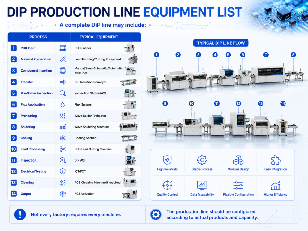
DIP Production Line Equipment List
Not every factory requires every machine.
The production line should be configured according to actual products and capacity.
What Is a DIP Insertion Conveyor?
A DIP insertion conveyor provides a working area where operators insert through-hole components while PCBs move through the production line.
It can include:
- Adjustable conveyor speed
- Lighting
- Component trays
- Workstations
- ESD protection
- Storage areas
- Adjustable working width
A well-designed insertion conveyor improves operator efficiency and production flow.
What Is a Wave Soldering Machine?
The wave soldering machine is one of the most important pieces of equipment in THT manufacturing.
Its primary purpose is to solder multiple through-hole component leads in a continuous production process.
A modern machine typically includes:
- Fluxing system
- Preheating zones
- Solder pot
- Wave generation system
- Conveyor
- Cooling system
- Process controls
Machine selection should consider PCB dimensions, production capacity, solder alloy, component density, and process requirements.
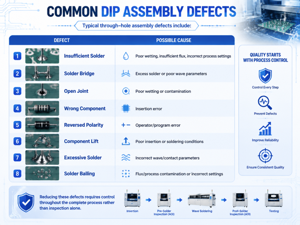
How to Improve DIP Production Line Quality
Several practices can improve THT assembly quality.
Standardize Component Insertion
Use:
- Work instructions
- Component positioning guides
- Polarity identification
- Error-proof fixtures
Optimize Wave Soldering Parameters
Regularly monitor:
- Preheat temperature
- Conveyor speed
- Solder temperature
- Wave height
- Flux application
Add AOI
Automated inspection helps identify defects consistently.
Maintain Equipment
Preventive maintenance reduces process variation and unplanned downtime.
Train Operators
Manual insertion quality depends heavily on operator skills and standardized procedures.
Track Quality Data
Monitor:
- First-Pass Yield
- Defect rate
- Rework rate
- Solder defect categories
- Equipment downtime
Data can help identify recurring problems.
Manual vs Automatic DIP Production Line
Many factories use a hybrid solution.
For example:
Manual Insertion + Automatic Conveyor + Wave Soldering + AOI + Automatic Testing
This approach can provide a practical balance between flexibility, automation, and investment.
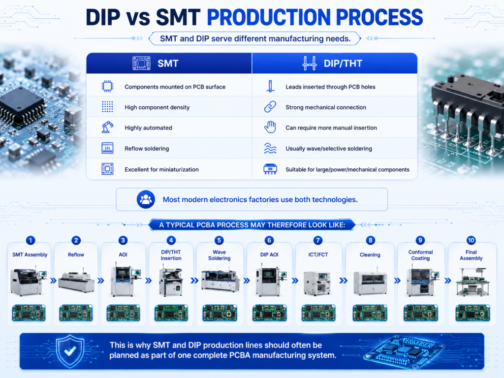
DIP vs SMT Production Process
SMT and DIP serve different manufacturing needs.
Most modern electronics factories use both technologies.
A typical PCBA process may therefore look like:
SMT Assembly → Reflow → AOI → DIP/THT Insertion → Wave Soldering → DIP AOI → ICT/FCT → Cleaning → Conformal Coating → Final Assembly
This is why SMT and DIP production lines should often be planned as part of one complete PCBA manufacturing system.
Wave Soldering vs Selective Soldering
Not every THT PCB is suitable for conventional wave soldering.
Wave Soldering
Best suited when many through-hole joints can be soldered simultaneously.
Advantages include:
- High throughput
- Mature process
- Efficient mass production
Selective Soldering
Applies solder only to selected locations.
It can be useful when:
- SMT components are located close to THT joints
- Only a few through-hole components require soldering
- Complex PCB layouts prevent full wave soldering
- Precise solder control is required
Manufacturers should evaluate PCB design before deciding between the two processes.
How to Configure a DIP Production Line
Before purchasing equipment, determine:
- PCB dimensions
- PCB thickness
- Component types
- Through-hole component quantity
- Required production capacity
- Product mix
- Insertion method
- Solder alloy
- Flux type
- Inspection requirements
- Testing requirements
- Factory space
- Labor availability
- Automation target
- Future production plans
These parameters determine the correct line configuration.
How Much Does a DIP Production Line Cost?
There is no fixed price for a complete DIP line.
Cost depends on:
- Automation level
- Number of insertion stations
- Conveyor length
- Wave soldering machine configuration
- AOI requirements
- ICT/FCT equipment
- PCB handling automation
- Cleaning equipment
- Traceability
- Installation and commissioning
A simple manual insertion and wave soldering setup requires significantly less investment than a highly automated THT production line.
Manufacturers should therefore request a quotation based on their actual PCB and production requirements.
How to Choose a DIP Production Line Supplier
A reliable supplier should provide more than individual equipment.
Look for capabilities including:
- Process analysis
- Equipment selection
- Production capacity calculation
- Factory layout planning
- Line balancing
- Wave soldering solutions
- DIP AOI
- Conveyor integration
- Testing solutions
- Installation
- Commissioning
- Operator training
- Maintenance
- Spare parts
- Technical support
For a new PCB assembly factory, working with a supplier capable of integrating SMT, DIP, coating, and inspection processes can simplify the overall project.
Why Choose Fuliu Electronics?
Established in 2014, Fuliu Electronics is dedicated to providing customers with high-quality PCBA intelligent manufacturing solutions and professional technical services.
With extensive experience in the electronics manufacturing industry, we provide equipment and integrated solutions covering SMT, DIP/THT, inspection, conformal coating, and supporting PCBA processes.
Our SMT equipment portfolio includes pick and place machines from internationally recognized brands such as Fuji, Panasonic, ASM, Yamaha, JUKI, and Hanwha, together with ERSA reflow ovens from Germany, MagicRay SPI/AOI inspection systems, automatic solder paste printers, high-quality pre-owned SMT equipment, spare parts, equipment leasing, and maintenance services.
For DIP/THT production, Fuliu Electronics can support customers with:
- DIP insertion conveyors
- Through-hole assembly workstations
- Component preparation equipment
- Wave soldering machines
- Selective soldering solutions
- DIP AOI inspection
- PCB conveyors and handling equipment
- ICT/FCT integration
- PCB cleaning equipment
- Production line automation
- Factory layout planning
- Installation and commissioning
- Operator training
- Technical support
Based on the customer’s PCB dimensions, component types, production capacity, product mix, quality requirements, factory layout, automation level, and budget, our engineering team can configure a suitable DIP production line.
Fuliu Electronics is actively expanding across India, Vietnam, the Philippines, Indonesia, the Middle East, South Africa, and Europe, supporting electronics manufacturers with flexible and scalable PCBA production solutions.
Conclusion
So, how does a DIP production line work?
The complete process typically involves:
Component Preparation → Through-Hole Insertion → Inspection → Fluxing → Preheating → Wave/Selective Soldering → Cooling → Lead Processing → AOI → ICT/FCT → Cleaning → Final Inspection
The exact production flow varies according to PCB design, component type, production volume, and quality requirements.
For high-mix, low-volume manufacturing, manual or semi-automatic insertion may provide the best flexibility. For stable, high-volume products, greater automation can improve throughput and consistency.
More importantly, DIP should not be considered separately from the rest of PCBA manufacturing. In many factories, SMT, DIP/THT, testing, cleaning, and conformal coating form one continuous production system.
Designing these processes together helps manufacturers improve line balance, reduce unnecessary handling, increase first-pass yield, and create a more efficient PCB assembly factory.
Frequently Asked Questions
A DIP production line is a PCB assembly line primarily used to insert and solder through-hole electronic components. It may include component preparation, insertion, wave soldering, AOI, testing, cleaning, and PCB handling equipment.
Typical equipment includes DIP insertion conveyors, component preparation machines, wave or selective soldering equipment, AOI, lead cutting machines, ICT/FCT stations, conveyors, and optional cleaning equipment.
SMT components are mounted directly onto PCB surfaces and typically soldered using a reflow oven. Through-hole components are inserted through PCB holes and commonly soldered using wave or selective soldering.
Yes. THT/DIP assembly remains important for connectors, transformers, relays, power components, terminals, and other parts requiring strong mechanical connections or specific electrical characteristics.
Wave soldering allows multiple through-hole component leads to be soldered in a continuous process by passing the PCB over a controlled wave of molten solder.
Wave soldering contacts a broader area of the PCB with solder, while selective soldering targets specific through-hole joints. Selective soldering is useful for complex mixed-technology assemblies.