
Choosing a DIP production line is not simply a matter of buying a wave soldering machine and several conveyors.
A complete DIP/THT assembly process may involve:
- Component preparation
- Through-hole insertion
- PCB handling
- Pre-solder inspection
- Fluxing
- Preheating
- Wave or selective soldering
- Cooling
- Inspection
- Testing
- Rework
- Traceability
The correct line configuration depends heavily on the PCB, BOM, production volume, product mix, component structure, automation target, and factory layout.
For this reason, manufacturers planning a new line should start with production data rather than equipment models.
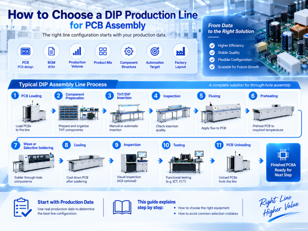
A typical process may look like:
PCB Loading → Component Preparation → THT/DIP Insertion → Inspection → Fluxing → Preheating → Wave or Selective Soldering → Cooling → Inspection → Testing → PCB Unloading
How to Choose a DIP Production Line for PCB Assembly
This guide explains how to choose a DIP production line for PCB assembly step by step and how to avoid common equipment selection mistakes.
First, Understand What a DIP Production Line Actually Is
In strict technical terminology, DIP means Dual In-line Package.
However, in many electronics factories, the terms DIP line and DIP assembly are commonly used to describe the broader through-hole assembly process.
The technically broader term is THT, or Through-Hole Technology.
A DIP/THT production line can handle components such as:
- Connectors
- Terminal blocks
- Relays
- Transformers
- Switches
- Large capacitors
- Pin headers
- Selected power components
- Other through-hole devices
Some of these components are true DIP packages, while many are not.
For production line planning, the actual component list matters far more than terminology.
Step 1: Analyze the PCB Dimensions
PCB dimensions are among the first data points required when selecting equipment.
You should provide:
- PCB length
- PCB width
- PCB thickness
- Panel dimensions
- Maximum board weight
- Maximum component height
These dimensions influence the selection of:
- PCB loaders
- Conveyors
- Insertion workstations
- Wave soldering machines
- Selective soldering machines
- Unloaders
- Inspection equipment
For example, purchasing a machine based only on current PCB width may create problems if future products use wider panels.
At the same time, oversizing every machine may increase investment and floor-space requirements unnecessarily.
The objective is to select equipment that supports current production while leaving reasonable flexibility for expected future products.
Step 2: Review the BOM in Detail
The Bill of Materials, or BOM, is one of the most important documents in DIP line planning.
The BOM helps identify:
- Number of THT components
- Component types
- Component dimensions
- Lead structures
- Polarity requirements
- Component packaging
- Components suitable for automatic insertion
- Components requiring manual insertion
Two PCBs of the same physical size may need completely different production lines because their component structures are different.
For example:
PCB A
- 10 connectors
- 4 relays
- 2 transformers
- 6 large capacitors
PCB B
- 60 standardized through-hole components
- Minimal irregular components
PCB A may depend heavily on manual insertion.
PCB B may offer more opportunities for automated or semi-automated insertion.
Therefore, line selection should always begin with BOM analysis.
Step 3: Classify the THT Components
After reviewing the BOM, classify the through-hole components into categories.
Possible groups include:
Standard Components
These may have:
- Regular lead spacing
- Consistent geometry
- Standard packaging
- High repetition
They may be more suitable for automated preparation or insertion.
Irregular Components
These can include:
- Large transformers
- Relays
- Large connectors
- Complex switches
- Heavy components
Manual insertion may remain more practical.
Polarized Components
These require additional attention during assembly.
Examples can include:
- Electrolytic capacitors
- Diodes
- Certain connectors
Work instructions and inspection should clearly control orientation.
This classification helps determine the required automation level.
Step 4: Determine the Target Production Capacity
Do not select a DIP line without a clear capacity target.
Manufacturers should define:
- Boards per hour
- Boards per shift
- Daily output
- Number of working shifts
- Expected utilization
- Future capacity requirement
Capacity should be calculated for the complete line rather than one machine.
For example:
- Component preparation: 50 boards/hour
- THT insertion: 25 boards/hour
- Wave soldering: 70 boards/hour
- Inspection: 40 boards/hour
- Testing: 30 boards/hour
The real line output will be constrained by the slowest effective process.
In this example, THT insertion is the main bottleneck at approximately 25 boards per hour.
Buying a faster wave soldering machine would not solve the capacity problem.

Step 5: Choose Manual, Semi-Automatic, or Automatic Insertion
THT insertion is often the most labor-intensive stage.
Manufacturers typically have three options.
Manual DIP/THT Insertion
Manual insertion is suitable when:
- Production volume is relatively low
- Product mix is high
- Components are irregular
- Changeovers are frequent
- Labor flexibility is important
A manual insertion area may include:
- PCB conveyors
- Component racks
- Lighting
- ESD protection
- Work instructions
- Fixtures where required
Manual production can be highly flexible but may require more operators.
Semi-Automatic Insertion
Semi-automatic production can improve efficiency while maintaining flexibility.
Possible systems include:
- Component preparation machines
- Guided insertion systems
- Pick-to-light material systems
- Semi-automatic component handling
- Automated PCB transfer
This is often a practical option for medium-volume EMS manufacturing.
Automatic THT Insertion
Automatic insertion may be suitable when:
- Production volume is high
- Product demand is stable
- Components are standardized
- Packaging supports automatic feeding
- The same products repeat frequently
Automatic insertion can reduce repetitive labor, but it is not suitable for every THT component.
The best solution may therefore be:
Automatic insertion for suitable components + manual insertion for irregular components.
Step 6: Choose Between Wave and Selective Soldering
Soldering technology has a major influence on the complete DIP line configuration.
When to Choose Wave Soldering
Wave soldering can be suitable when:
- The PCB contains many THT joints
- Board design supports wave soldering
- Production volume is medium or high
- Continuous throughput is important
A typical process includes:
Fluxing → Preheating → Solder Wave → Cooling
A wave soldering machine commonly integrates:
- Spray fluxing
- Preheating
- Conveyor
- Solder pot
- Wave system
- Cooling
When to Choose Selective Soldering
Selective soldering may be preferable when:
- Only a small number of THT joints require soldering
- There are bottom-side SMT components
- Certain areas must avoid broad solder contact
- Products are complex or high-mix
- Localized soldering is required
Selective soldering can provide programmable soldering for specific joints.
Some factories use both technologies for different products.
Step 7: Evaluate Component Preparation Requirements
Component preparation is often overlooked when purchasing a DIP production line.
However, poor component preparation can slow the entire insertion process.
Components may require:
- Lead cutting
- Lead forming
- Bending
- Straightening
- Sorting
- Kitting
Possible equipment includes:
- Lead cutting machines
- Resistor forming machines
- Capacitor lead processing machines
- General component forming equipment
The correct equipment depends on the actual BOM.
Step 8: Plan PCB Handling and Conveyors
Conveyors are essential for connecting production stages.
A DIP line may use:
- PCB loaders
- Standard conveyors
- Insertion conveyors
- Inspection conveyors
- Cooling conveyors
- Buffers
- PCB unloaders
The handling system should support:
- PCB dimensions
- Product flow
- Operator access
- Production direction
- Required buffers
- Factory layout
Poor PCB handling can create unnecessary labor even when the main machines are automated.
Step 9: Decide How Much Pre-Solder Inspection Is Needed
Inspection before soldering can prevent insertion errors from reaching the soldering stage.
Typical checks include:
- Missing components
- Wrong components
- Incorrect polarity
- Wrong orientation
- Bent leads
- Improper insertion depth
- Component misalignment
Low-volume production may use manual inspection.
Higher-volume production may use:
- Vision assistance
- Barcode verification
- Automated inspection where suitable
Pre-solder inspection can reduce expensive post-solder rework.
Step 10: Plan Post-Solder Inspection
After soldering, the PCB should be checked according to production requirements.
Typical solder defects can include:
- Solder bridges
- Insufficient solder
- Poor wetting
- Incomplete hole fill
- Excessive solder
- Icicles
- Solder balls
Possible inspection methods include:
- Visual inspection
- Magnification systems
- Digital microscopes
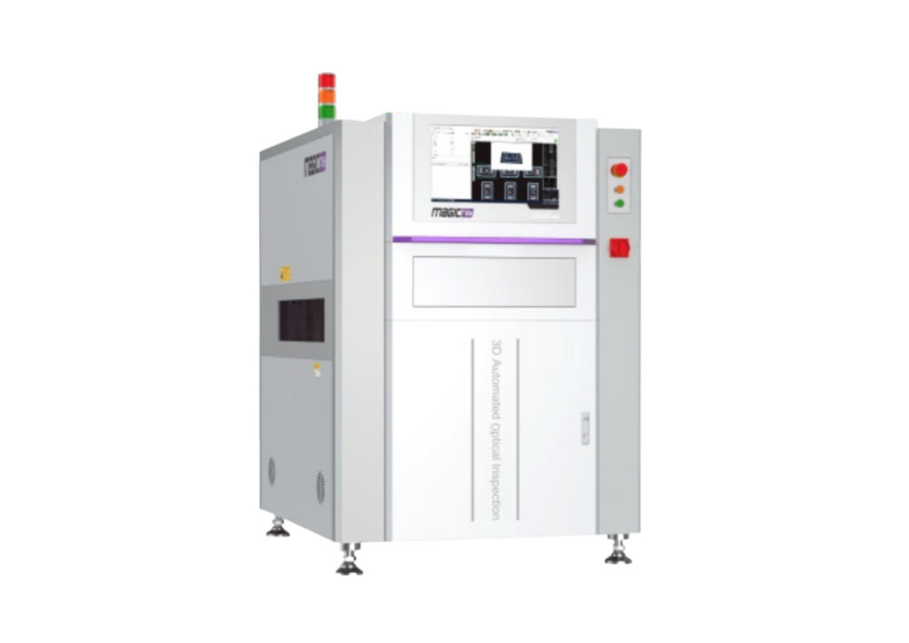
- AOI where suitable
- X-ray for selected structures
Not every line needs every inspection technology.
The inspection plan should match the PCB and quality requirements.
Step 11: Include Testing in the Line Capacity Calculation
Testing is often ignored during equipment planning.
Depending on the product, testing may include:
- ICT
- Functional testing
- Power-on testing
- Programming
- Communication testing
- I/O testing
- Calibration
Suppose the DIP line can assemble 50 boards per hour but one functional test station can process only 20 boards per hour.
The line cannot deliver 50 finished boards per hour unless testing capacity is increased.
Possible solutions include:
- Parallel test stations
- Improved fixtures
- Automated test sequences
- Better material flow
Always calculate production capacity through final testing.
Step 12: Evaluate Product Mix and Changeover Frequency
A line designed for one stable product can be very different from a line serving an EMS factory with frequent product changes.
High-Mix Production
Priorities usually include:
- Flexible insertion
- Quick changeover
- Adjustable conveyors
- Flexible fixtures
- Program management
- Easy material preparation
Manual or semi-automatic insertion may remain important.
High-Volume Production
Priorities may include:
- Higher automation
- Automatic insertion
- Continuous PCB handling
- Higher soldering throughput
- Automated inspection
- Traceability
The best line is the one that matches the actual production model.
Step 13: Plan the Factory Layout
Machine selection and factory layout should be considered together.
Important factors include:
- Available floor space
- Material entrance
- PCB flow direction
- Operator movement
- Component storage
- WIP areas
- Rework area
- Testing area
- Maintenance access
- Exhaust
- Power
- Compressed air where required
A good production line should minimize unnecessary movement.
A typical straight-line layout may be:
Loading → Insertion → Inspection → Wave Soldering → Cooling → Inspection → Testing
However, U-shaped or segmented layouts may be more practical depending on factory space.
Step 14: Check Utilities Before Buying Equipment
Equipment installation requires suitable factory utilities.
Depending on machine configuration, requirements may include:
- Electrical power
- Compressed air
- Exhaust
- Ventilation
- Nitrogen
- Network connections
- ESD infrastructure
These requirements should be confirmed during the planning stage rather than after equipment arrives.
Step 15: Consider ESD and Fume Extraction
A complete line includes more than production machines.
Manufacturers should also plan suitable:
- ESD workstations
- Grounding
- Wrist straps
- ESD mats or flooring
- Fume extraction
- Ventilation
Fluxing, soldering, and manual rework processes can produce fumes that need appropriate extraction according to factory and local requirements.
Step 16: Decide Whether Traceability Is Required
Some manufacturing environments require production data tracking.
Traceability can involve:
- PCB serial number
- Barcode scanning
- Production time
- Machine information
- Program
- Operator
- Inspection result
- Test result
The level of traceability should be selected according to customer and product requirements.
Not every factory requires the same system.
Step 17: Compare New and Pre-Owned Equipment
A DIP line can be built using:
- New equipment
- Pre-owned equipment
- A combination of both
New Equipment May Be Suitable When:
- New machine condition is important
- Latest machine functions are required
- Long-term standardization is planned
- Warranty support is a priority
Pre-Owned Equipment May Be Suitable When:
- Investment budget is limited
- Faster capacity expansion is required
- Proven equipment platforms meet the process needs
Before selecting pre-owned machines, evaluate:
- Machine condition
- Configuration
- Maintenance history
- Spare parts availability
- Software
- Technical support
- Production compatibility
The correct comparison is based on total cost of ownership, not purchase price alone.
Step 18: Calculate Total Project Cost
The price of individual machines is only part of a DIP line project.
The total investment may include:
- Main equipment
- Conveyors
- Component preparation machines
- Fixtures and tooling
- Exhaust systems
- Installation
- Training
- Initial spare parts
- Utilities
- Transportation
- Import-related costs where applicable
- Factory modifications
- Testing equipment
Manufacturers should evaluate the full project before making a purchasing decision.
Three Typical DIP Production Line Configurations
Configuration 1: Low-Volume, High-Mix Line
A basic line may include:
Manual PCB Loading → Component Preparation → Manual THT Insertion → Inspection → Manual/Wave/Selective Soldering → Inspection → Testing
Suitable for:
- Prototype production
- Small batches
- Frequent product changes
- High-mix EMS manufacturing
Main priority:
Flexibility
Configuration 2: Semi-Automatic DIP Line
A typical configuration may be:
Automatic Loader → Insertion Conveyor → Manual/Semi-Automatic THT Insertion → Inspection Conveyor → Wave Soldering → Cooling Conveyor → Unloader → Inspection → Testing
Suitable for:
- Medium-volume production
- Multiple product models
- Factories seeking labor reduction
- Balanced automation investment
Main priority:
Balance between flexibility and efficiency
Configuration 3: Highly Automated DIP Line
A higher-automation line can include:
Automatic Loader → Automatic THT Insertion → Manual Special Component Insertion → Automated Inspection → Wave/Selective Soldering → Cooling → Automated Inspection → Testing → Unloader
Optional systems can include:
- Barcode readers
- Buffers
- Material feeding systems
- Traceability
- MES connection
- Automated test handling
Suitable for:
- Stable products
- Higher production volumes
- Repetitive component structures
Main priority:
Throughput and process consistency
How to Avoid Over-Automating a DIP Line
Maximum automation is not always the most efficient choice.
A factory may invest heavily in an automatic insertion machine only to discover that:
- Many components cannot be automatically fed
- Changeover is frequent
- Product volumes are too low
- The machine has low utilization
- Testing remains the bottleneck
A better approach is to automate processes that provide clear value.
This may include:
- PCB loading
- PCB transportation
- Component preparation
- Standardized insertion
- Fluxing
- Wave soldering
- Inspection
- Testing
while retaining manual work for highly irregular components.
How to Evaluate DIP Line Suppliers
When comparing suppliers, look beyond machine prices.
A capable production line supplier should be able to discuss:
- PCB and BOM analysis
- Capacity calculation
- Equipment configuration
- Line balancing
- Factory layout
- Machine compatibility
- Installation
- Training
- Spare parts
- Technical support
- Maintenance
A supplier should also explain why specific equipment is recommended rather than simply offering the largest or fastest machine.
A Practical DIP Line Selection Checklist
Before requesting a quotation, prepare the following information:
- PCB dimensions and thickness
- Panel dimensions
- BOM
- THT component list
- Component photos or datasheets where useful
- Component packaging
- Number of THT components per board
- Target boards per hour
- Daily or monthly production target
- Number of shifts
- Product mix
- Changeover frequency
- Wave or selective soldering preference
- Inspection requirements
- Testing requirements
- Traceability requirements
- Existing equipment
- Factory layout
- Utility conditions
- Desired automation level
- Investment budget
- Future expansion plans
Providing this information can significantly improve the accuracy of a production line proposal.
Integrating the DIP Line with an SMT Production Line
Many modern PCB factories use both SMT and THT.
A complete mixed-technology process may be:
PCB Loader → Solder Paste Printer → SPI → SMT Pick and Place → Reflow Oven → AOI → THT Insertion → Wave/Selective Soldering → Inspection → Testing
This means the DIP line should not always be planned independently.
Important questions include:
- What is the SMT line output?
- How much WIP can be buffered?
- Can THT insertion support SMT output?
- Can soldering support insertion output?
- Can testing support total output?
A balanced SMT + DIP process can reduce excessive WIP and improve overall factory efficiency.
DIP and Complete PCBA Production Line Solutions from Fuliu Electronics
Established in 2014, Fuliu Electronics is dedicated to providing customers with high-quality PCBA intelligent manufacturing solutions and services.
With extensive experience in the SMT industry, we specialize in dependable equipment, professional technical support, and complete SMT and PCBA production line solutions.
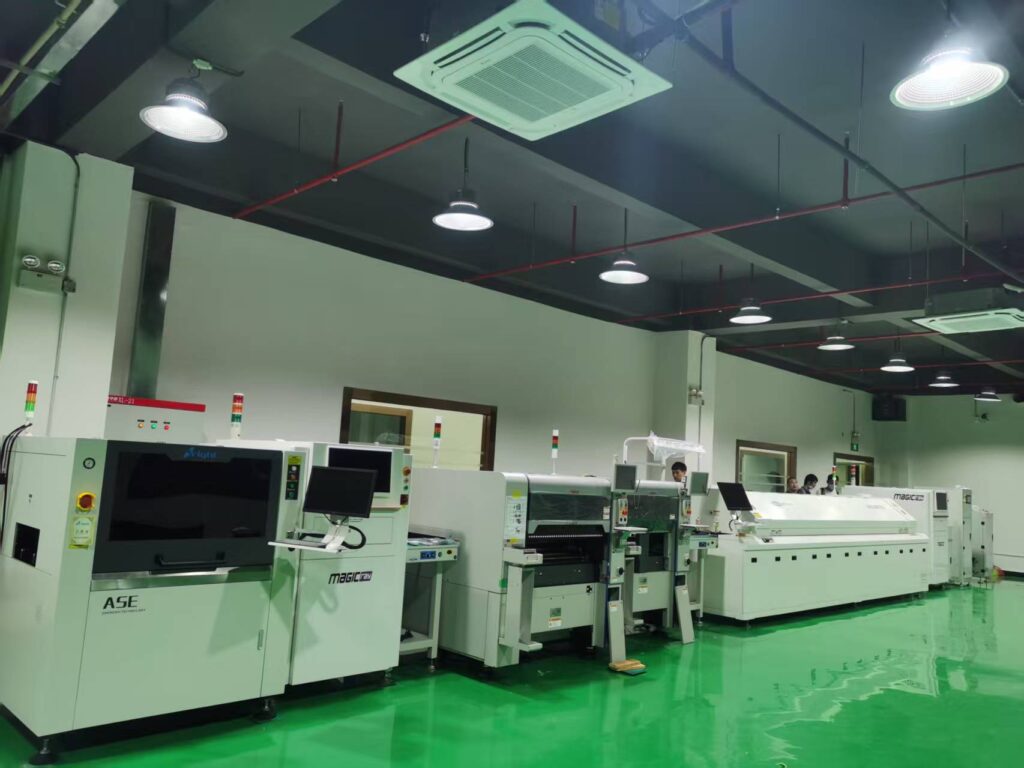
Our product portfolio includes SMT pick and place machines from Fuji, Panasonic, ASM, Yamaha, JUKI, and Hanwha, together with ERSA reflow ovens from Germany, MagicRay SPI/AOI inspection systems, automatic solder paste printers, supporting PCBA equipment, pre-owned SMT equipment, SMT spare parts, machine leasing, and maintenance services.
For customers choosing or upgrading a DIP/THT production line, Fuliu Electronics can help evaluate:
- PCB dimensions
- BOM
- THT component structure
- Component packaging
- Target capacity
- Product mix
- Manual vs automatic insertion
- Wave vs selective soldering
- Inspection and testing requirements
- Existing equipment
- Factory layout
- Utility requirements
- Automation level
- Investment budget
Rather than selecting machines individually, manufacturers can evaluate the complete process from component preparation and insertion through soldering, inspection, testing, and material handling.
As part of our global growth strategy, Fuliu Electronics is actively expanding into international markets, with key focus areas including India, Vietnam, the Philippines, Indonesia, the Middle East, South Africa, and Europe.
Frequently Asked Questions
Start with the PCB, BOM, THT component list, target capacity, and production model. These factors determine the required equipment and automation level.
A line may include PCB loaders, conveyors, component preparation equipment, insertion stations, inspection conveyors, wave or selective soldering, cooling, unloaders, inspection, testing, and rework equipment.
Manual insertion is often suitable for high-mix or irregular components. Automatic insertion can be more suitable for standardized components and stable high-volume production.
Wave soldering is often suitable when many THT joints need continuous processing. Selective soldering may be better when only specific joints require soldering or PCB design limits wave soldering.
Calculate the effective cycle time of component preparation, insertion, soldering, inspection, and testing. The bottleneck process will usually limit total line output.
No. Highly automated equipment may not be economical for high-mix, low-volume products or irregular THT components.