
A DIP production line is a PCB assembly production system used to install and solder through-hole components after, or alongside, the SMT assembly process.
In electronics factories, the term “DIP line” is commonly used to describe the production area responsible for components such as:
- Connectors
- Terminal blocks
- Relays
- Transformers
- Pin headers
- Switches
- Large capacitors
- Selected power components
A typical process may look like:
PCB Loading → Component Preparation → THT/DIP Insertion → Pre-Solder Inspection → Fluxing → Preheating → Wave or Selective Soldering → Cooling → Inspection → Testing → PCB Unloading
However, there is no single standard DIP production line suitable for every factory.
The correct configuration depends on:
- PCB dimensions
- BOM
- THT component types
- Component packaging
- Production capacity
- Product mix
- Soldering method
- Automation target
- Inspection requirements
- Testing requirements
- Factory layout
- Investment budget
What Is a DIP Production Line? A Complete Guide
This guide explains what a DIP production line is, what equipment it includes, how the process works, and how manufacturers can configure a suitable line for PCB assembly.
What Does DIP Mean in PCB Manufacturing?
Technically, DIP means Dual In-line Package.
A DIP component normally has two parallel rows of leads that pass through holes in the PCB.
However, in many electronics factories, the term “DIP assembly” is used more broadly to refer to through-hole assembly.
The more technically accurate term is THT, or Through-Hole Technology.
THT describes the mounting method in which component leads are inserted through holes in the PCB and soldered on the opposite side.
Therefore:
Every conventional through-hole DIP component is a THT component, but not every THT component is a DIP component.
For example, a transformer, terminal block, radial capacitor, or connector may be through-hole without being a DIP package.
Despite this distinction, “DIP production line” remains a common manufacturing and equipment-purchasing term.
What Is the Purpose of a DIP Production Line?
The purpose of a DIP line is to complete the through-hole assembly processes that are not handled by the SMT line.
A modern PCB may contain both:
- Surface-mount components
- Through-hole components
SMT equipment handles most small and high-density surface-mount parts.
The DIP/THT line then processes components that may require:
- Greater mechanical support
- Larger physical size
- Higher-current connections
- Special component geometry
- Manual insertion
- Wave or selective soldering
For this reason, SMT and DIP production are often complementary rather than competing processes.
What Products Commonly Require DIP/THT Assembly?
Through-hole assembly remains common in many electronics products.
Examples include:
- Industrial control systems
- Power supplies
- Automotive electronics
- Home appliance controllers
- Energy equipment
- Communication products
- Charging equipment
- LED power systems
- Factory automation
- Motor control products
Consumer electronics containing large connectors or power components
The actual proportion of SMT and THT components varies by product design.
Typical DIP Production Line Process
A complete DIP assembly flow can include:
PCB Loading → Component Preparation → THT Insertion → Inspection → Fluxing → Preheating → Soldering → Cooling → Inspection → Testing → Unloading
Each stage affects production quality and efficiency.
Step 1: PCB Loading
The first process is loading the PCB into the production line.
This can be done manually with a magazine loader
Through an automatic conveyor connection from an upstream process
Automatic PCB loaders are useful when:
- Production volume is higher
- Continuous PCB transport is required
- Labor reduction is a priority
Selection should consider:
- PCB width
- PCB length
- Board thickness
- Panel weight
- Magazine dimensions
- Conveyor direction
Step 2: Component Preparation
Many through-hole components require preparation before insertion.
Possible operations include:
- Lead cutting
- Lead forming
- Bending
- Straightening
- Taping removal
- Component sorting
- Kitting
Typical component preparation equipment can include:
- Radial lead forming machines
- Axial lead forming machines
- Lead cutting machines
- Component forming tools
Proper preparation can improve insertion speed and soldering consistency.
Step 3: THT Component Insertion
Components are then inserted into the PCB.
There are three main approaches.
Manual Insertion
Operators insert components by hand.
This is common for:
- Transformers
- Large capacitors
- Relays
- Connectors
- Terminal blocks
- Irregular components
Manual insertion offers high flexibility and is practical for high-mix or lower-volume production.
Semi-Automatic Insertion
Semi-automatic systems can assist with:
- Component presentation
- Work instructions
- PCB positioning
- Process control
This reduces some manual handling while preserving flexibility.
Automatic THT Insertion
Automatic insertion machines can process selected components that have suitable geometry and packaging.
Automation is most practical for components with:
Stable dimensions
Standardized packaging
Consistent orientation
Sufficient production volume
Not every through-hole component is suitable for automatic insertion.
For many factories, a hybrid strategy is more practical:
Automatic insertion for suitable parts + manual insertion for large or irregular components
Step 4: Pre-Solder Inspection
After insertion, the PCB should be inspected before soldering.
Typical checks include:
- Missing components
- Wrong components
- Incorrect polarity
- Incorrect orientation
- Bent leads
- Component height
- Insertion depth
- Loose components
Pre-solder inspection is important because fixing insertion errors before soldering is usually easier than performing rework afterward.
Step 5: Flux Application
If the board is processed by wave soldering, flux is applied to the solder side.
Flux helps prepare metal surfaces for solder wetting.
A wave soldering machine may use a spray fluxing system.
Important process variables include:
- Flux type
- Flux quantity
- Spray width
- Coverage
- Uniformity
Flux conditions should match the PCB, solder alloy, and production process.
Step 6: Preheating
After fluxing, the board enters preheating.
Preheating can help:
- Activate flux
- Raise PCB temperature gradually
- Reduce sudden thermal changes
- Improve soldering stability
- Prepare higher-thermal-mass assemblies
- The required preheat conditions depend on:
- PCB thickness
- Copper distribution
- Component thermal mass
- Flux chemistry
- Solder alloy
- Conveyor speed
There is no universal preheat setting suitable for every PCB.
Step 7: Wave Soldering
Wave soldering is one of the most common soldering methods in DIP production.
The PCB passes over a controlled wave of molten solder.
Through-hole leads and pads on the underside of the PCB contact the solder wave and form solder joints.
Wave soldering can be efficient when:
The board contains many THT joints
Production volume is medium or high
The PCB underside is suitable for wave contact
Continuous production is required
Important wave soldering parameters include:
- Flux application
- Preheat
- Solder temperature
- Conveyor speed
- Wave height
- Contact time
- PCB orientation
- Machine maintenance
Step 8: Selective Soldering
Selective soldering is an alternative to wave soldering.
Instead of exposing a broader underside area to solder, the machine processes programmed joints or regions.
Selective soldering may be preferable when:
- Only a few THT joints are present
- Bottom-side SMT components restrict wave soldering
- Certain PCB areas must avoid solder contact
- Product mix is high
- Joint locations are localized
A typical selective soldering process includes:
Selective Fluxing → Preheating → Programmed Soldering
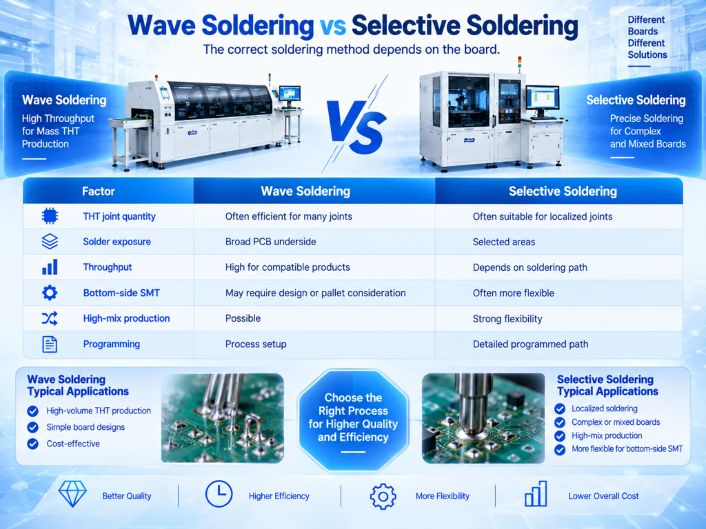
Wave Soldering vs Selective Soldering
The correct soldering method depends on the board.
Neither method is universally better.
The PCB design and required production rate should determine the choice.
Step 9: Cooling
After soldering, the PCB should cool before downstream handling.
Cooling may be provided by:
- Integrated machine cooling
- Cooling conveyor
- Controlled airflow
The goal is to allow solder joints to solidify before inspection and testing.
Step 10: Post-Solder Inspection
After soldering, the PCB should be checked for defects.
Common wave or selective soldering defects can include:
- Solder bridges
- Insufficient solder
- Poor wetting
- Incomplete hole fill
- Excessive solder
- Icicles
- Solder balls
Inspection methods can include:
- Visual inspection
- Magnification
- AOI where suitable
- X-ray for selected hidden structures
Inspection requirements depend on PCB design and quality requirements.
Step 11: Electrical and Functional Testing
Testing should be considered part of the production line, not an isolated downstream process.
Possible testing methods include:
- ICT
- Functional testing
- Programming
- Power-on testing
- Communication testing
- I/O testing
The correct test method depends on the product.
Testing capacity should also be included in line balancing.
Step 12: PCB Unloading
Completed PCBAs may be:
- Collected manually
- Loaded into magazines
- Sent to final assembly
- Sent to additional testing
- Sent to conformal coating
- Sent to packaging
The unloading method should match the downstream manufacturing process.
What Equipment Is Used in a DIP Production Line?
A complete DIP production line may include:
- PCB loader
- PCB conveyors
- Component preparation machines
- Material racks
- Manual insertion workstations
- Semi-automatic insertion systems
- Automatic THT insertion machines
- Inspection conveyors
- Wave soldering machine
- Selective soldering machine
- Cooling conveyor
- PCB unloader
- AOI where applicable
- ICT
- Functional test equipment
- Rework station
- ESD equipment
- Fume extraction system
Not every factory needs every machine.
The equipment list should be determined by the actual product.
What Is a Typical Manual DIP Line?
A basic manual line may include:
Manual PCB Loading → Component Preparation → Manual Insertion → Pre-Solder Inspection → Wave Soldering → Manual Inspection → Testing
This configuration may be suitable for:
- Low-volume production
- High product mix
- Prototypes
- Frequent product changes
- Advantages include:
- Lower initial investment
- High component flexibility
- Simple changeover
However, labor requirements are higher and output depends strongly on operator efficiency.
What Is a Semi-Automatic DIP Line?
A semi-automatic line may include:
Automatic Loader → Insertion Conveyor → Manual/Semi-Automatic THT Insertion → Inspection Conveyor → Wave Soldering → Cooling → Automatic Unloader → Inspection → Testing
This is common for factories that want to:
- Reduce PCB handling
- Increase production consistency
- Improve material flow
- Maintain flexibility for irregular components
For many manufacturers, semi-automation provides a practical balance between flexibility and productivity.
What Is a Highly Automated DIP Line?
A more automated DIP production line may include:
Automatic Loader → Automatic/Semi-Automatic THT Insertion → Automated Inspection → Wave/Selective Soldering → Cooling → Inspection → Testing → Automatic Unloader
Additional functions may include:
- Barcode identification
- Automatic width adjustment
- Traceability
- Recipe management
- Production data collection
- Higher automation is most attractive when:
- Production volume is high
- Product design is stable
- Component packaging supports automation
- Labor reduction is important
However, over-automation can increase cost without improving actual line output.
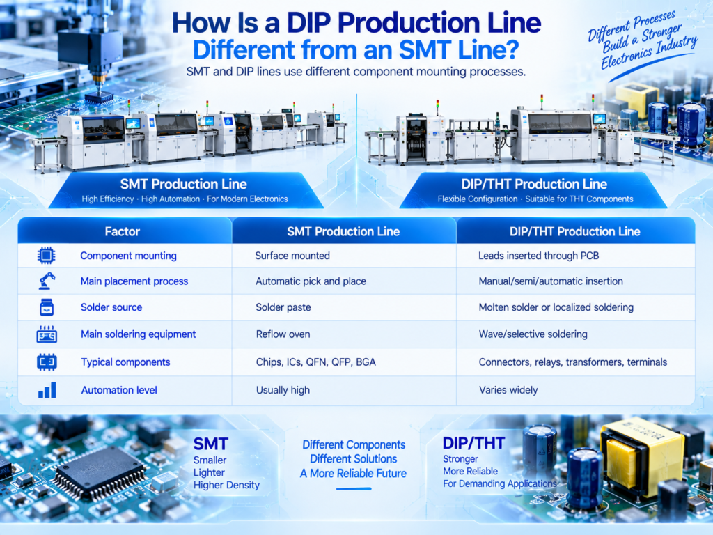
How Is a DIP Production Line Different from an SMT Line?
SMT and DIP lines use different component mounting processes.
Modern electronics factories frequently use both.
How SMT and DIP Lines Work Together
For mixed-technology PCBAs, SMT is usually completed first.
A typical complete process is:
PCB Loader → Solder Paste Printer → SPI → SMT Placement → Reflow → AOI → THT Insertion → Wave/Selective Soldering → Inspection → Testing
This allows high-density surface-mount components and large through-hole components to be assembled on the same PCB.
Why Is THT Still Used If SMT Is More Automated?
SMT dominates modern electronics manufacturing, but THT remains useful for certain component and product requirements.
Through-hole mounting may be selected for:
- Large connectors
- Terminal blocks
- Transformers
- Relays
- Large capacitors
- Electromechanical components
- Selected power components
It may also provide additional mechanical support in applications where the component or connection is mechanically loaded.
However, THT should not be considered universally stronger or more reliable than SMT.
The correct mounting method depends on component, PCB, mechanical, electrical, and production requirements.
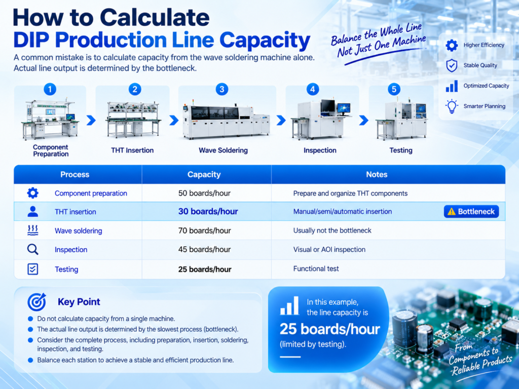
How to Calculate DIP Production Line Capacity
A common mistake is to calculate capacity from the wave soldering machine alone.
Actual line output is determined by the bottleneck.
For example:
Although wave soldering can process 70 boards per hour, the complete line may only deliver around 25 finished boards per hour if testing remains the bottleneck.
Therefore, manufacturers should evaluate the whole process.
Why THT Insertion Is Often a Bottleneck
THT insertion may require significant manual work because many components are:
- Large
- Heavy
- Irregular
- Differently packaged
- Difficult to automate
Factories can improve insertion efficiency through:
- Component kitting
- Better workstation layout
- Parallel operators
- Automatic component preparation
- Semi-automatic insertion
- Automatic insertion for suitable components
- Standardized work instructions
The goal is not necessarily to automate every component.
The goal is to balance the complete production line.
How Many Operators Does a DIP Line Need?
There is no fixed number.
Operator requirements depend on:
- Number of THT components per PCB
- Manual insertion time
- Target cycle time
- Product mix
- Component preparation
- Inspection
- Testing
- Automation level
For manual insertion, line balancing can be performed by measuring operator cycle time.
For example, if one PCB requires 120 seconds of total manual insertion and the target takt time is 30 seconds, multiple balanced workstations may be required.
DIP Production Line Layout
Factory layout affects productivity.
A good layout should support:
- Logical material flow
- Minimal PCB handling
- Short operator movement
- Component replenishment
- Maintenance access
- Exhaust routing
- Inspection
- Testing
- Rework
A simple linear layout can be:
Loading → Preparation → Insertion → Soldering → Inspection → Testing → Unloading
A U-shaped layout may be useful where floor space is limited or operators need to support multiple processes.
Factory Utilities Required for a DIP Line
Depending on equipment configuration, utilities can include:
- Electrical power
- Compressed air
- Exhaust
- Ventilation
- Nitrogen where required
- ESD grounding
Wave and selective soldering equipment may have specific exhaust and electrical requirements.
These should be reviewed before machine installation.
ESD Control in DIP Assembly
THT assembly still involves electronic components that may be sensitive to electrostatic discharge.
An ESD-controlled production area may include:
- ESD workbenches
- Grounding systems
- ESD flooring or mats
- Wrist straps
- ESD-safe storage
- Suitable material handling
The exact ESD program depends on factory and product requirements.
Fume Extraction for Soldering Equipment
Wave and selective soldering may generate process fumes.
Factories should plan appropriate:
- Exhaust connections
- Ventilation
- Fume extraction
- Maintenance access
Requirements depend on equipment design, flux chemistry, factory environment, and local regulations.
Material Management in a DIP Production Line
Unlike SMT reels, THT components may arrive in many packaging formats.
Examples include:
- Tubes
- Trays
- Bags
- Taped radial components
- Taped axial components
- Bulk packaging
Good material preparation and kitting can reduce operator searching and insertion errors.
Workstations should clearly separate:
- Component part numbers
- Polarity
- Position
- Quantity
How to Improve DIP Production Line Efficiency
Manufacturers can improve efficiency by focusing on:
- Bottleneck analysis
- Component preparation
- Operator balancing
- Material kitting
- Conveyor flow
- Changeover reduction
- Wave soldering stability
- Defect reduction
- Testing capacity
- Preventive maintenance
Improving only one machine may not improve finished output.
For example, increasing wave soldering capacity provides little benefit if manual insertion remains the limiting process.
Common DIP Production Line Problems
Factories may experience:
Slow Manual Insertion
Possible improvements include:
- Better workstations
- Component kitting
- Parallel operators
- Automated preparation
- Partial insertion automation
Frequent Soldering Defects
Common defects can include:
- Solder bridges
- Poor wetting
- Incomplete hole fill
- Insufficient solder
Review:
- Flux
- Preheat
- Solder temperature
- Conveyor speed
- PCB design
- Component solderability
- Equipment maintenance
- Excessive WIP
High WIP usually indicates poor process balance.
Compare cycle times across:
- Insertion
- Soldering
- Inspection
- Testing
Long Changeover Time
Changeover can be improved through:
- Standardized work
- Material preparation
- Recipe management
- Adjustable conveyors
- Organized tooling
High Rework
High rework reduces effective capacity.
Track defects by:
- Component
- Station
- Operator
- PCB model
- Soldering process
Then address root causes rather than only increasing inspection.
Wave Soldering Machine Selection
When choosing a wave soldering machine, consider:
- PCB dimensions
- Conveyor width
- Fluxing system
- Preheat capacity
- Solder pot
- Wave configuration
- Conveyor speed
- Cooling
- Control system
- Maintenance access
For high-thermal-mass products, preheat and thermal capacity deserve particular attention.
Selective Soldering Machine Selection
For selective soldering, evaluate:
- THT joint locations
- Bottom-side clearance
- Nozzle access
- Nozzle sizes
- Fluxing accuracy
- Preheat
- Soldering path
- Cycle time
- Product changeover
- Conveyor compatibility
A representative PCB should be reviewed before machine selection.
Should You Automate the DIP Line?
Automation can improve:
- Material flow
- Repeatability
- Labor efficiency
- Capacity
- Traceability
But automation should be applied selectively.
Do not assume every THT process should be automated.
Automation makes the most sense when:
- Tasks are repetitive
- Product design is stable
- Component packaging is suitable
- Production volume justifies investment
- Labor or capacity is a real bottleneck
High-mix production may benefit more from semi-automation than from a fully automated line.
New vs Pre-Owned DIP Production Line Equipment
Manufacturers can use:
- New equipment
- Pre-owned equipment
- A combination of both
Pre-owned equipment can be useful when manufacturers want to:
- Reduce initial investment
- Expand capacity
- Use established equipment platforms
However, equipment should be evaluated for:
- Mechanical condition
- Control system
- Maintenance history
- Spare parts availability
- Technical support
- Compatibility with current products
Total cost of ownership should be considered rather than machine price alone.
How Much Does a DIP Production Line Cost?
There is no universal fixed cost.
Investment depends on:
- Automation level
- Number of insertion stations
- Automatic insertion equipment
- Wave vs selective soldering
- PCB handling
- Inspection
- Testing
- Exhaust
- Tooling
- Installation
- Training
- Spare parts
A basic manual line requires significantly less investment than a highly automated THT line.
For this reason, suppliers should first understand the product and production target before preparing a quotation.
DIP, THT and PCBA Production Solutions from Fuliu Electronics
Established in 2014, Fuliu Electronics is dedicated to providing customers with high-quality PCBA intelligent manufacturing solutions and services.
With extensive experience in the SMT industry, we specialize in dependable equipment, professional technical support, and complete SMT and PCBA production line solutions.
Our product portfolio includes SMT pick and place machines from Fuji, Panasonic, ASM, Yamaha, JUKI, and Hanwha, together with ERSA reflow ovens from Germany, MagicRay SPI/AOI inspection systems, automatic solder paste printers, supporting PCBA equipment, pre-owned SMT equipment, SMT spare parts, machine leasing, and maintenance services.
For manufacturers planning a new DIP/THT line, Fuliu Electronics can help evaluate:
- PCB dimensions
- BOM
- THT component structure
- Component packaging
- Manual vs automatic insertion
- Target capacity
- Product mix
- Wave vs selective soldering
- Inspection and testing
- Existing SMT equipment
- Factory layout
- Automation requirements
- Investment budget
Manufacturers can also evaluate the complete mixed-production process:
SMT Assembly → THT Insertion → Wave/Selective Soldering → Inspection → Testing
This helps ensure that equipment capacity is balanced across the entire PCBA manufacturing process.
As part of our global growth strategy, Fuliu Electronics is actively expanding into international markets, with key focus areas including India, Vietnam, the Philippines, Indonesia, the Middle East, South Africa, and Europe.
Frequently Asked Questions
A DIP production line is a PCB assembly system used to prepare, insert, solder, inspect, and test through-hole components.
Not exactly. DIP is a specific dual in-line package type, while THT is the broader through-hole mounting technology. In factory terminology, “DIP line” is often used to describe a general THT assembly line.
Typical equipment can include PCB loaders, conveyors, component preparation machines, insertion workstations, wave or selective soldering machines, inspection equipment, testing stations, and unloaders.
No. Some products may be better suited to selective soldering or manual soldering.
SMT lines mount surface-mount components and normally use reflow soldering. DIP/THT lines insert component leads through PCB holes and normally use wave, selective, or manual soldering.
Yes. Many PCBAs use SMT for small components and THT for connectors, transformers, relays, terminals, and other larger components.